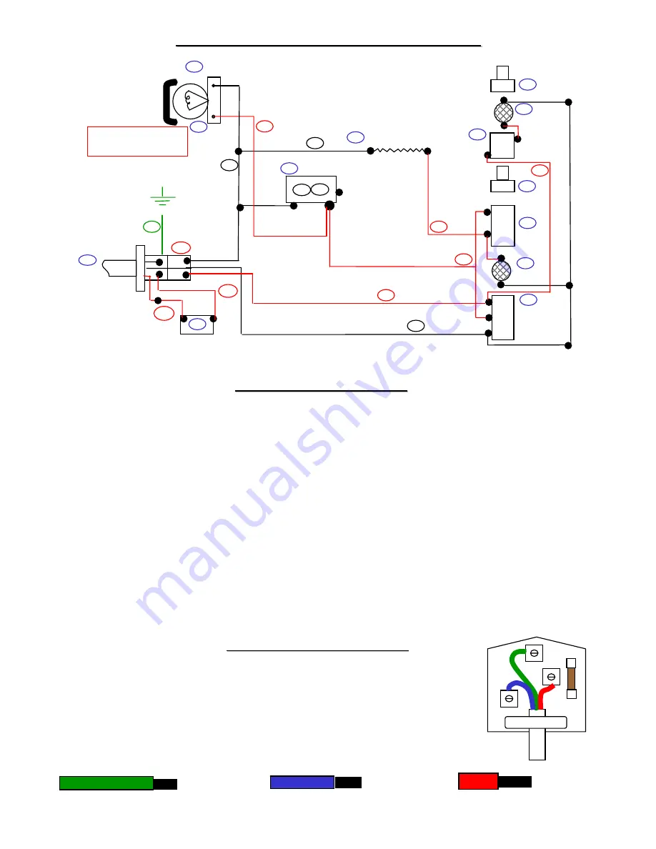
Wiring Diagram
Wiring Diagram
-
-
Classic 50 Oven
Classic 50 Oven
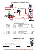
Electrical Component List
Electrical Component List
1
Mains Flex
190201
13 Display Area - High Temp Bulb 400125
2
Wires Red
CO9001
14 Fan Motor
700000
3
Wires Red
CO9002
15 Control knobs 190304
4
Wires Red
CO9003 16 Main Oven Element (2.6kW) 7000022
6
Wires Red
CO9004
17 Thermal Cut Out 190222
7.
Wires Black
CO9005
18 Thermostat 190303V
8
Wires Black
CO9006
19 Neon Indicator (with tails) 190303A
9
Wires Earth
CO9007
20 Fan on/off switch
190001a
10
Wires Red
CO9008
21 Rectangular Top Bulb Housing 500121
11
Wires Red
CO9009
complete with lens cover
12
Mains Connector
190306V
22 90 minute timer T-90
Neutral = BLACK Line
Live = RED Line
3
2
15
16
7
14
7
8
Main Oven Element
Top Bulb Holder
Fan Motor
1
2
Thermal
Cut Out
18
19
20
T’Stat
1
2
3
Fan
Oven
Switch
Timer
Neon
4
2
19
Neon
15
21
9
6
L
L
N
N
17
10
1
Mains Flex
Earth
Stud
13
12
11
22
WIRING INSTRUCTIONS
WIRING INSTRUCTIONS
•
Prepare all 3 wires using trimming template
•
Loosen cord grip
• Wire in the sequence: Neutral – Live – Earth
•
Ensure terminal screws are tight
• Always use 13 amp (Brown) fuse
• Tighten cord grip onto cord before replacing cover
L
CORD GRIP
FU
SE
E
N
If in doubt contact a qualified electrician.
THIS APPLIANCE MUST BE EARTHED
NEUTRAL / BLUE OR BLACK
25mm
8mm
EARTH - GREEN OR YELLOW / GREEN
40mm
8mm
LIVE / BROWN OR RED
8mm
12mm

