background image

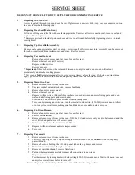
SERVICE SHEET

SERVICE SHEET

DISCONNECT FROM ELECTRICITY SUPPLY BEFORE COMMENCING SERVICE

1.

Replacing top oven bulb

Access is gained through top oven door.  Lever off glass cover, unscrew bulb - replace cover ensuring cut-out 
in cover is over bulb housing side.

2.

Replacing Door Seal (Main Oven)

Lift door off hinges and lie flat with seal facing upwards.  Unscrew all screws next to seal, remove seal and 
replace.  Reverse process.
* Ensure seal is tucked inside lip on cast door and is even all round before fully tightening screws - do 

not

over tighten!

3.

Replacing Top Oven Bulb Assembly

Remove outer canopy, stainless steel oven top, 8 screws, pull off wire connectors.  Assembly can be removed 
through oven after pushing in clamps around sides.  Reverse process.

4.

Replacing Thermal Cut-out

Remove fan motor access panel at rear of oven (2 screws)

Remove thermal cut out (2 screws)

Replace with new item

Reverse process

Important

- fibre washers must be replaced between cut-out plate and oven or oven will cut out 

prematurely and disable cooking process.
* Test oven at 

full

temperature and allow to cycle several times, before leaving.  If whole oven (including 

lights) go off, cut-off plate would need bending away from oven.   Re-test when cooled.

5.

Replacing Main Oven Fan

5.1

Remove element cover from inside oven

5.2

Unscrew central nut anticlockwise, remove fan blade

5.3

Remove fan motor access panel

5.4

Remove thermal cut out

Replace with new item. (Ensure fibre washers are used between fan motor fixing plate and oven 
wall and also fixing plate and screw heads)

Use stud loc and screws to prevent them from vibrating loose.

Test oven by turning fan switch on, turn thermostat to mid setting (150-200) towards neon.  Allow 
oven to cycle several times, making sure fan blade does not catch on element cover

6.

Replacing Fan Oven Element

6.1

Remove fan motor access panel at rear of oven (2 screws)

6.2

Pull off wire terminals

6.3

Remove element cover from inside oven.  NB: the 2 slotted screws only need to be loosened and the 
cover lifted and pulled over the screw heads

6.4

Remove central screw from element and lift out

6.5

Replace with new element and reverse procedure

6.6

Test oven

7.

Replacing Thermostat

7.1

Remove element cover from inside oven 

7.2

Carefully open slightly the 2 clips holding thermostat sensor.  Move 

in line

with hole, capillary 

passes through.

7.3

Remove 8 screws holding the L/H side panel (when facing doors) and remove

7.4

Retract thermostat sensor through oven side

7.5

Remove control knob and 2 screws from front

7.7

Pull out thermostat and carefully transfer all connections to new item

Replace in reverse order

Test thermostat by turning knob with mid setting (150-200) towards neon.  Wait until neon goes out 
and cycles several times before turning off. 

Ensure 

all

operational and safety checks are conducted before leaving machine.

Summary of Contents for CLASSIC 50

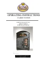
Page 1: ...OPERATING INSTRUCTIONS OPERATING INSTRUCTIONS CLASSIC 50 OVEN CLASSIC 50 OVEN BEDIENUNGSANLEITUNG MODE D EMPLOI GEBRUIKSAANWIJZING PLEASE READ CAREFULLY Rev 5 01 06 2010 ...

Page 2: ... outside of the potatoes before the inside is cooked moderate heat for longer is recommended All King Edward ovens MUST be operated by suitably trained staff Under NO circumstances should children come into contact with or operate this appliance Taking the trays out and positioning the potatoes before loading will enable you to gain the maximum capacity from your baker This product may increase th...

Page 3: ...f the holding oven the potatoes will inevitably reduce in core temperature The display oven is intentionally at a lower temperature to prevent the potato from over cooking this also helps to prolong the display life of the potato Despite being prepared and cooked in the same way the same batch of potatoes can produce different results Please use the method of baking that suits you best and gives y...

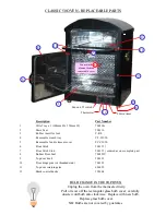
Page 4: ...t 8 Rubber Door Seal 700229V 9 Top door knob 500121 10 Door hinge pins s s threaded stud 700122 11 Top door retaining arm 600022 12 Black control knobs 190304 8 12 Thermostat 90 min timer 10 11 Fan motor element behind removable cover Fan on off switch 5 9 3 1 BULB CHANGE IN THE TOP OVEN BULB CHANGE IN THE TOP OVEN Unplug the oven from the mains electricity Pull or lever off the rectangular glass ...

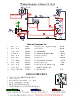
Page 5: ...es Red CO9009 complete with lens cover 12 Mains Connector 190306V 22 90 minute timer T 90 Neutral BLACK Line Live RED Line 3 2 15 16 7 14 7 8 Main Oven Element Top Bulb Holder Fan Motor 1 2 Thermal Cut Out 18 19 20 T Stat 1 2 3 Fan Oven Switch Timer Neon 4 2 19 Neon 15 21 9 6 L L N N 17 10 1 Mains Flex Earth Stud 13 12 11 22 WIRING INSTRUCTIONS WIRING INSTRUCTIONS Prepare all 3 wires using trimmin...

Page 6: ...nticlockwise remove fan blade 5 3 Remove fan motor access panel 5 4 Remove thermal cut out Replace with new item Ensure fibre washers are used between fan motor fixing plate and oven wall and also fixing plate and screw heads Use stud loc and screws to prevent them from vibrating loose Test oven by turning fan switch on turn thermostat to mid setting 150 200 towards neon Allow oven to cycle severa...

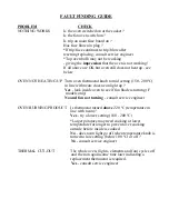
Page 7: ...ith neon does neon light up Yes look inside oven to see if fan blade is turning F models only No and fan not turning consult service engineer OVEN BURNING PRODUCT Is thermostat turned above 220 ºC temperature in line with neon Yes try a lower setting 180 200 ºC Larger potatoes may need cooking at lower temperature for longer to prevent over cooking outside before inside is cooked No does neon ligh...

Page 8: ...ntee Please check your fuses and electricity supply before calling out an engineer as service calls requested in error will be charged at the normal rate Please have the equipment sited where it is easily accessible to the engineer and where there is adequate room to work In the case of an oven please ensure the product has not been used within 6 hours of the engineers visit and that it has cooled...

Reviews: