background image

3

EN

1. 

General warnings   


1.1 - 

Safety warnings


CAUTION! 

-  This  manual  contains  important  safety  instructions  and 

warnings.  Incorrect  installation  could  lead  to  serious  injury. 

Before starting, please read all sections of the manual care-

fully. If you are unsure about something, stop installation im-

mediately and contact KING-gates Customer Service for as-

sistance.
- Important: please retain this manual for future maintenance 

work and product disposal.

1.2 - 

Installation warnings

• 

Before beginning the installation procedure, check that this prod-

uct  is  suitable  for  its  intended  use.  If  unsuitable,  do  NOT  proceed 
with installation.
The contents of this manual refer to an installation like the one shown 
in

.

• 

Considering  the  risk  situations  that  may  arise  during  installation 

phases and use of the product, the automation must be installed in 
observance of the following warnings:
- Ensure there is a system device which is a means of disconnection 
from the supply mains. This device must have a contact separation in 
all poles which ensures full disconnection under overvoltage category 
III conditions.
-  All  installation  and  maintenance  operations  must  be  carried  out 
with the automation system switched off and the power supply dis-
connected. If the disconnection device is not visible from where the 
automation system has been installed, a sign must be attached to 
it  before  attempting  any  work.  The  sign  should  read:  “WARNING! 
MAINTENANCE IN PROGRESS”.
- The product must be connected to a power supply line equipped 
with safety grounding system.
- Take care not to crush, bang, drop or spill any kind of liquid on the 
automation system during installation. Do not keep the product close 
to sources of heat or open 

 Doing so may damage it, corrupt 

it or lead to hazardous situations. If this were to happen, stop instal-
lation immediately and contact KING-gates Customer Service.
- Do not make alterations to the product in any way. Improper use 
can only lead to malfunctions. The manufacturer declines all liability 
for damage caused by arbitrary 

 to the product.

- This product is not intended for use by people (including children) 
with  reduced  physical,  sensory  or  mental  capabilities  or  who  lack 
experience and knowledge, unless they have been given supervision 
or instruction concerning the use of the product by a person respon-
sible for their safety.
- The product is not intended as an intruder protection system. If an 

 protection system is required, the automation must be inte-

grated with other devices.
- Do not allow children to play with the 

 control devices. Keep 

remote control devices out of their reach as well.
- The packing materials of the product must be disposed of in com-
pliance with local regulations.
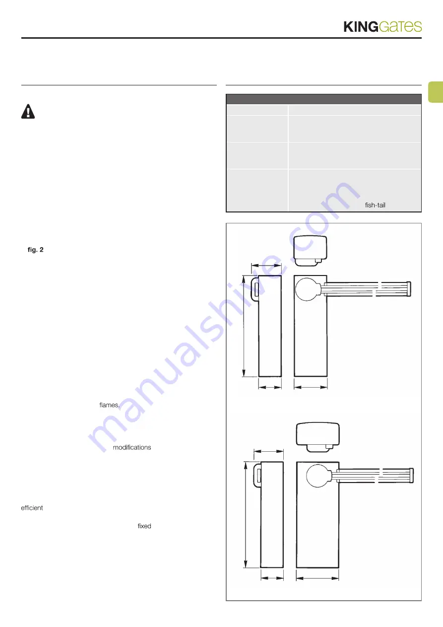
2. 

Description of the 

product

Table 1

Model

Description

OPEN 4000

Automatic boom gate in galvanised, painted 
steel with an opening time of 3 to 5 seconds; 
maximum net opening is 4 metres.

OPEN 6000

Automatic boom gate in galvanised, painted 
steel with an opening time of 5 to 8 seconds; 
maximum net opening is 6 metres.

Note: OPEN4000

The standard 
supply includes

A

 - Cubicle with 24 V DC gearmotor

B

 - Electronic control unit

C

 - Connection for bar

D

 - Anchorage base with 

 clamps

OPEN 6000

Max 6 m.

360

220

420

05

01

OPEN 4000

Max 4 m.

360

220

320

00

01

1

Summary of Contents for OPEN 6000

Page 1: ...EN Automatic boom gate mechanical installation Installation and use instructions and warnings FR Barri re automatique Installation m canique Instructions et avertissements pour l installation et l uti...

Page 2: ......

Page 3: ...urezza Durante l installazione maneggiare con cura l automatismo evi tando schiacciamenti urti cadute o contatto con liquidi di qualsiasi natura Non mettere il prodotto vicino a fonti di calore n espo...

Page 4: ...14 15 10 8 7 6 5 4 1 Armadio 2 Sblocco 3 Flangia di attacco asta 4 Ammortizzatore di sicurezza con fermo 5 Motoriduttore 6 Leva uscita motoriduttore 7 Molla di bilanciamento 8 Tirante di regolazione m...

Page 5: ...co asta nella posizione di funzionamento 05 Regolare manualmente i due eccentrici per il rallentamento ve dere paragrafo 1 6 2 1 4 1 3 Installazione della barriera 01 Annegare la base di ancoraggio in...

Page 6: ...ttamente bilancia ta quando rimarr a 45 senza cadere verso il basso o salire verso l alto Qualora si utilizzi un asta molto corta senza alcun accessorio la potenza della molla sar eccessiva attaccare...

Page 7: ...nding system Take care not to crush bang drop or spill any kind of liquid on the automation system during installation Do not keep the product close to sources of heat or open Doing so may damage it c...

Page 8: ...13 9 14 15 10 8 7 6 5 4 1 Cubicle 2 Unlock device 3 Bar connecting flange 4 Shock absorber with safety stop 5 Gearmotor 6 Gearmotor external lever 7 Balancing spring 8 Spring adjustment tie rod 9 Hou...

Page 9: ...roller instructions 04 Tighten the bar connecting flange in the functioning position 05 Adjust by hand the two slowing down eccentrics see par 1 6 2 1 4 1 3 Installing the boom gate 01 Bury the suppli...

Page 10: ...ced when it stays at an angle of 45 without falling or rising If you are using a very short bar without any accessories the power of the spring will be far too strong in this case connect the spring t...

Page 11: ...s crasements les chocs les chutes ou tout contact avec des liquides de quelque nature que ce soit Ne laissez pas le produit proximit de sources de chaleur ni expos des vives Cela pourrait l endommager...

Page 12: ...6 5 4 1 Armoire 2 D blocage 3 Bride de fixation barre 4 Amortisseur de s curit avec but e 5 Moto r ducteur 6 Levier sortie moto r ducteur 7 Ressort d quilibrage 8 Tirant de r glage ressort 9 Logement...

Page 13: ...te lectronique 04 Visser la bride de fixation de la barre dans la position de fonc tionnement 05 R gler la main les deux excentriques pour le ralentissement voir paragraphe 1 6 2 1 4 1 3 Installation...

Page 14: ...sera correctement quilibr e quand elle restera 45 sans tomber vers le bas ou monter vers le haut Si on utilise une barre tr s courte sans aucun accessoire la puissance du ressort sera excessive fixer...

Page 15: ...conectarse a una l nea de alimentaci n dotada de puesta a tierra de seguridad Durante la instalaci n maneje la automatizaci n con cuidado evi tando su aplastamiento ca da o contacto con cualquier tip...

Page 16: ...rmario 2 Desbloqueo 3 Brida de uni n de la barrera 4 Amortiguador con tope de seguridad 5 Motorreductor 6 Palanca exterior del motorreductor 7 Muelle de equilibrado 8 Tensor de regulaci n del muelle 9...

Page 17: ...Enrosque la brida de uni n de la barrera en la posici n de fun cionamiento 05 Regule manualmente las dos exc ntricas para la ralentizaci n v ase 1 6 2 1 4 1 3 Instalaci n de la barrera 01 Introduzca l...

Page 18: ...brada cuando quede a 45 sin que se caiga o se suba En el caso de que utilice una barrera muy corta y sin ning n accesorio la potencia del muelle ser excesiva por lo tanto enganche el muelle en el 2 ag...

Page 19: ...5 7 Working temperature C Min Max 20 70 Working cycle 100 Motor weight kg 46 54 FR Caract ristiques techniques Unit de mesure OPEN 4000 OPEN 6000 Alimentation Vac 50 Hz 230 230 Vdc 24 24 Puissance ab...

Page 20: ...tails Dati del costruttore Manufacturer s details Timbro Stamp Azienda Company Localit Address Provincia Province Recapito telefonico Tel Referente Contact person King Gates S r l Phone 39 0434 737082...

Reviews: