background image

2

EN

Contents

Important 

notice 


1. Description of the product 


4

2.  Installation 

4

3.  Electrical connections 

4

3.1 - Electrical hookup 


4

3.2 - Operational tests 

5

3.3 - Adjusting the pause time 


5

3.4 - Available functions   


5

3.5 - Description of definitions 

            6

3.6 - Two-way traffic light 

6

3.7 - Description of the functioning modes 

7

3.8 - Charge card also battery powered 

7

4.  Technical features of the unit 

8

5. CE declaration of conformity 

9

Important notice

We  are  obliged  to  remind  you  that  you  are  working  on  equipment 
classified in the following category:

“Automatic gates and doors”, which are considered to be especially 
“Dangerous”; you must make them as “Safe” 

as reasonably pos

-

sible!

Only qualified, expert personnel must carry out the installation and 
any servicing required, making the best possible job of it and in ac

-

cordance with the following laws, standards and directives (norms, 
decrees of the President of the Republic and law decrees are only 
valid for Italy; EEC Directives are, on the other hand, applicable for 
the whole of Europe):

- UNI 8612 (Motorised gates and doors: construction criteria and ac

-

cident prevention equipment)
-  DPR  N°  46  of  5/03/1990  (Standards  for  the  safety  of  electrical 

installations, authorised personnel)

-  Dlgs  N°  459/96  of  24/07/96  (EEC  directive  89/392,  “Machinery 

Directive”)

-  Dlgs  N°  615/96  of  12/11/96  (EEC  directive  89/336,  Directive  on 

Electromagnetic Compatibility)

-  Dlgs  N°  626/96  of  26/11/96  (EEC  directive  93/68,  Low  Voltage 

Directive)
When designing and producing its products, Nice observes (as re-

gards the equipment) all the above standards but it is of paramount 

importance that the installer too (as regards the systems) strictly ob-
serves the same standards.

Unqualified personnel or those who do not know the standards appli

-

cable to the “Automatic gates and doors” category: 

must not install 

systems.

Whoever carries out systems without observing all the applicable 
standards:

 Will be held responsible for any damages that the 

system may cause!

1. 

Description of the 

product

The electronic card is suitable for controlling OPEN model road boom 
gates with 24 V DC motors.
This is an entirely new design where the actuator has a limit switch 
with a speed control system that makes it possible to reach the travel 
limits by means of a slowing down phase. In addition, the effort the 
motor is subject to during movement is promptly detected as well as 
any obstacles that may be in the path and in such an event direction 
is reversed.

The  most  advanced  techniques  and  sophisticated  components 

have been employed in the project to guarantee maximum immunity 

against interference, greater flexibility of use and the widest possible 

range of programmable functions.
It can be controlled “manually”, “semiautomatically” or “automatical-
ly”. There are also certain highly sophisticated functions like “Reclose 
immediately after Photocell” or “Reclose always”, “Flashing also in 
pause” as well as other operating functions such as “Gradual Start-
up” and “Slowing down” (a standard feature) plus a sensitive “Brake” 
that only comes into play if movement has to be stopped hastily.
The whole range of KING-GATES radio receivers can be inserted on 
the card.  
In view of the particularity of the product, before you start the instal-
lation and hookup, here is a brief description of the most important 
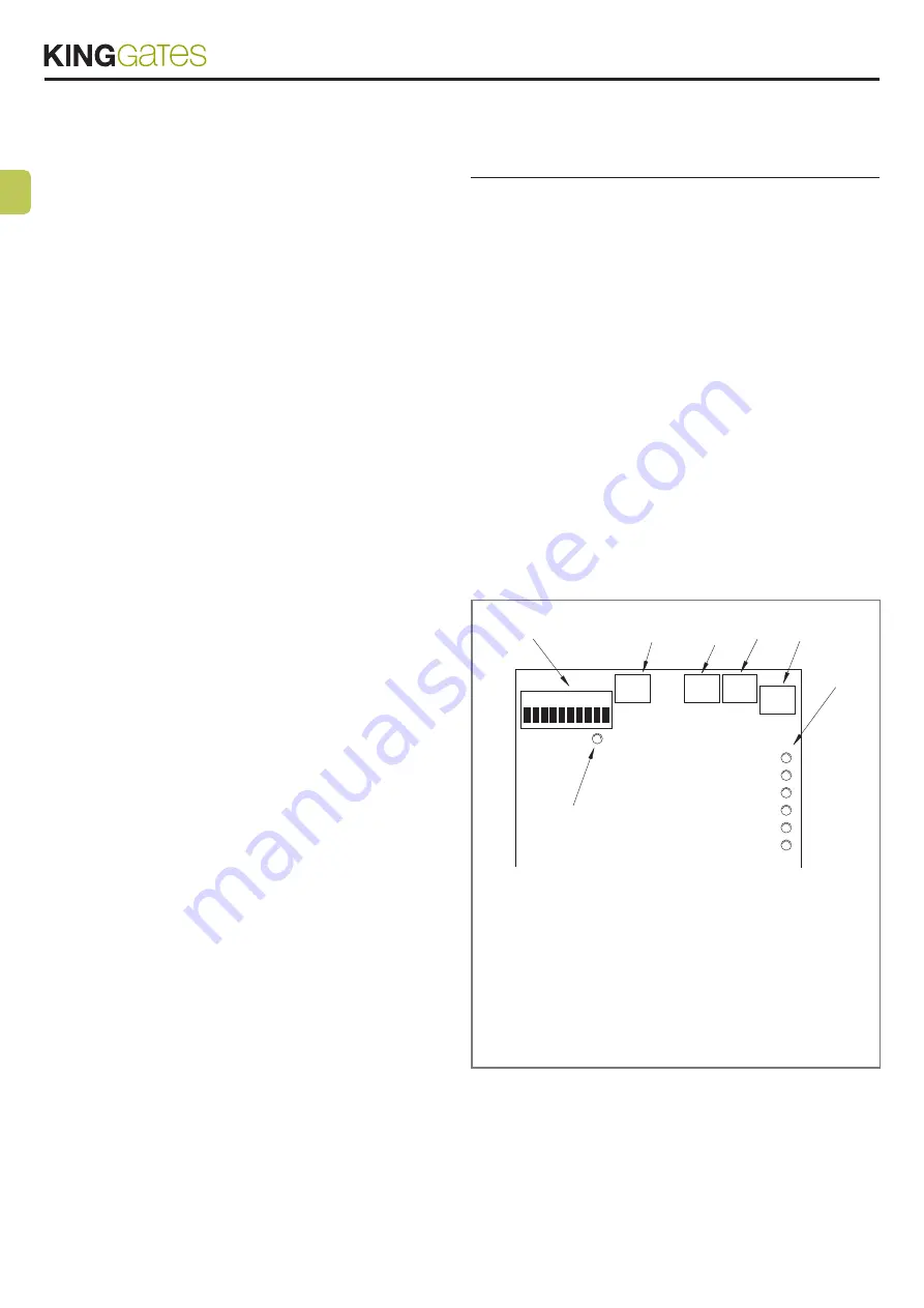
elements on the control card: 

(

1

) Set of micro dip-switches for selecting the FUNCTIONS

(

2

  LED that flashes at regular intervals and indicates that the unit is working correctly

(

3

) “STOP_AMPERE” trimmer to adjust friction and based on an ammetric 

measurement system
(

4

) “PAUSE TIME” trimmer to adjust pause time in the automatic functioning mode

(

5

) “WORKING FORCE” trimmer to adjust power to motor during the movement 

phase
(

6

) “SLOWING DOWN FORCE” trimmer to adjust power to motor during the slowing 

down phase
(

7

) Set of LEDs to signal the state of the command inputs

4

2

OK

1

3

5

6

7

CLOSE

OPEN

STEP BY STEP

PHOTO 2

PHOTO

STOP

STOP 

AMPERE

WORKING

FORCE

SLOWING

DOWN

FORCE

PAUSE

TIME

2

The OK LED (

2

) has the task of signalling the correct functioning of 

the  internal  logic  and  must  flash  at  1  second  intervals;  it  indicates 

that the internal microprocessor is active and waiting for commands. 
Whenever there is a change in the state of an input (whether it is a 

command input or function switch) a fast double flashing is gener

-

ated which happens even if the change does not have an immediate 

effect. Fast flashing at 5 second intervals means that the power volt

-

age is insufficient.

When the unit is powered, the indicator lights on the inputs (

7

) turn 

on if that particular input is active and hence 24 V DC control voltage 
is present. Normally, the LEDs on the safety inputs, PHOTOCELL, 

Summary of Contents for STAR OPEN 4000

Page 1: ...l uso EN Automatic boom gate electronic installation Installation and use instructions and warnings FR Barri re automatique Installation lectronique Instructions et avertissements pour l installation...

Page 2: ......

Page 3: ...senso di rotazione corretto ripetendo l opera zione descritta sopra 08 Regolare provvisoriamente i trimmer STOP_AMPERE e FOR ZA LAVORO al massimo della corsa TEMPO PAUSA al minimo e FORZA RALLENTAMEN...

Page 4: ...rogetto di nuova concezione infatti l attuatore dispone di finecorsa con un sistema di controllo della velocit che permette il raggiungimento dei limiti di corsa attraverso una fase di rallentamen to...

Page 5: ...Chi esegue detti interventi si rende responsabile di eventuali danni causati 3 Collegamenti elettrici Di seguito una breve descrizione dei possibili collegamenti della cen trale verso l esterno 1 2 2...

Page 6: ...velocit ridotta per altri 3 secondi 12 Regolare i Trimmer FORZA LAVORO e FORZA RALLENTA MENTO per ottenere che la manovra avvenga con la velocit e la spinta desiderata e che la fase di rallentamento...

Page 7: ...oi dopo 5 secondi 2 sec se in manuale inizia il movimento Switch 6 On Lampeggiante anche in Pausa Normalmente il lampeggiante viene attivato solo durante il movimen to in apertura o chiusura questa fu...

Page 8: ...do sull ingresso CHIUDE provocano la chiusura se il comando permane l asta rimarr bloccata in chiusura fino al cessare del comando solo dopo potr essere riaperta Un impulso su PASSO P provoca alternat...

Page 9: ...en turned 180 c Unplug the LIMIT SWITCH connector and replug it after it has been turned 180 07 See if rotation direction is right repeating the procedure de scribed above 08 Temporarily adjust the ST...

Page 10: ...limits by means of a slowing down phase In addition the effort the motor is subject to during movement is promptly detected as well as any obstacles that may be in the path and in such an event direc...

Page 11: ...se jobs shall be held re sponsible for any damage caused 3 Electrical connections Here is a brief description of the possible connections on the unit to the outside 1 2 230 V AC 230 V AC 50 60 Hz powe...

Page 12: ...ought to continue for a further 3 seconds at a slower speed 12 Adjust trimmers WORKING FORCE and SLOWING DOWN FORCE so that the manoeuvre is carried out at the speed and with the force required and th...

Page 13: ...t starts Switches 6 On Flashing also in Pause The flashing light is normally activated only during the opening and closing manoeuvres with this function the flashing light remains ac tive also during...

Page 14: ...cause a closing manoeuvre if the command remains the bar will stay locked in the closed position until the com mand ceases and only then can it be reopened A pulse on STEP BY STEP causes alternative o...

Page 15: ...remettre tourn de 180 c Extraire le connecteur FIN DE COURSE et le remettre tourn de 180 07 Contr ler de nouveau si le sens de rotation est correct en r p tant l op ration d crite plus haut 08 R gler...

Page 16: ...c moteur en courant continu 24 V Il s agit d un projet de conception nouvelle car en effet l actionneur dispose de micro interrupteurs de fin de course avec un syst me de contr le de la vitesse qui pe...

Page 17: ...ct des normes UNI 8612 et suivant les meilleures indications dict es par les r gles de l art Qui effectue ces interventions se rend responsable des ventuels dom mages qui en d coulent 3 Branchements l...

Page 18: ...entr e en jeu du ralentissement qui permet la poursuite de la course une vitesse r duite pendant 3 secondes de plus 12 R gler les Trimmers FORCE TRAVAIL et FORCE RALENTIS SEMENT pour obtenir que la ma...

Page 19: ...r s 5 secondes 2 s en mode manuel le mouvement commence Dip switch 6 On Clignotement galement en Pause Normalement le clignotant est activ seulement durant le mouve ment en ouverture ou en fermeture c...

Page 20: ...erm e Les impul sions de commande sur l entr e FERMETURE provoquent la ferme ture si la commande persiste la barre restera bloqu e en fermeture jusqu la cessation de la commande ce n est qu apr s qu e...

Page 21: ...siguiente manera a Desconecte la alimentaci n el ctrica de la barrera b Extraiga el conector MOTOR e introd zcalo nuevamente girado 180 c Extraiga el conector FIN DE CARRERA e introd zcalo nue vamente...

Page 22: ...tope con un sistema de control de la velocidad que permite alcanzar los l mites de carrera a trav s de una etapa de ralentizaci n adem s se detecta el esfuerzo al cual est sometido el motor durante e...

Page 23: ...A continuaci n describimos brevemente las posibles conexiones de la central hacia el exterior 1 2 230 Vca Alimentaci n el ctrica 230 Vca 50 60 Hz 3 4 Intermitente Salida para la conexi n a la luz inte...

Page 24: ...ue permite que la carrera contin e por otros 3 segundos a una velocidad lenta 12 Regule los trimmers FUERZA TRABAJO e FUERZA RALENTI ZACI N para que la maniobra se produzca a la velocidad y empuje des...

Page 25: ...modalidad manual inicia el movimiento Switch 6 On Intermitente en Pausa Normalmente la luz intermitente se acciona s lo durante el movi miento de apertura o cierre esta funci n prev que la luz interm...

Page 26: ...uevamente Los impulsos de mando en la entrada CIERRA producen el cierre si el mando contin a la barrera quedar bloqueada en cierre hasta que el mando finalice y s lo despu s se podr abrir nuevamente U...

Page 27: ...Declaration in accordance with Directives 2004 108 EC EMC 2006 42 EC MD annex II part B Declaration number K106 OPEN Rev 0 Language EN Name of manufacturer KING GATES S r l Address Via Malignani 42 3...

Page 28: ...tails Dati del costruttore Manufacturer s details Timbro Stamp Azienda Company Localit Address Provincia Province Recapito telefonico Tel Referente Contact person King Gates S r l Phone 39 0434 737082...

Reviews:

Related manuals for STAR OPEN 4000