


5
EN
Switches 1-2
Off Off
= “Manual” movement (Man Present)
On Off
= “Semiautomatic” movement
Off On
= “Automatic” movement (Automatic Closing)
On On
= “Aut Always Closes” movement
Switches 3
On
= Condominium function
Switches 4
On
= Cancels STOP in the Step-by-Step cycle
Switches 5
On
= Pre-flashing
Switches 6
On
= Flashing also in Pause
Switches 7
On
= Recloses straight after Photocell
(only if on Automatic)
Switches 8
On
= Safety (Photocell) also in opening
Switches 9
On
= Bar open indicator becomes traffic light in
the “one-way” mode
Switches 10
On
= Functioning in the “Traffic light in both
directions” mode
CAUTION! - Of course, with each switch OFF the function
described will not be activated.
3.5 -
Description of definitions
Below is a brief description of the functions that can be selected;
all the functions can be enabled or disabled without any limit even if
some combinations would have no sense and, therefore, not be car-
ried out (for instance, function 6, Flashing also in Pause, would not be
carried out if movement is in the manual mode).
Switches 1-2
Off Off
= “Manual” movement (Man Present)
On Off
= “Semiautomatic” movement
Off On
= “Automatic” movement (Automatic Closing)
On On
= “Aut Always Closes” movement
When in the “Manual” functioning mode, movement will only be car-
ried out while the command is being given (button pressed).
In the “Semiautomatic” mode just one command pulse is needed
and the complete manoeuvre will be carried out until it is either fully
open or fully closed. In the “Automatic” functioning mode one com-
mand pulse will cause an opening manoeuvre to be carried out fol-
lowed by a pause and then a closing manoeuvre.
The “Always Closes” function works if, subsequent to a temporary
power cut, the bar is still open; in this case, a closing manoeuvre is
started automatically preceded by 5 seconds of preflashing.
Switches 3
On
= Condominium function
In the Condominium functioning mode, once an opening manoeuvre
has started, for instance with a Step-by-Step pulse, it cannot be in-
terrupted by any other command pulses until it has finished.
During a closing manoeuvre, a new command pulse will stop the bar
and immediately reverse the direction, opening the bar.
Switches 4
On
= Cancels STOP in the Step-by-Step cycle
The Step-by-Step cycle is normally: OPEN-STOP-CLOSE-STOP;
in this functioning mode the Step-by-Step cycle becomes: OPEN-
CLOSE-OPEN so the bar can never stop midway, but only when
completely open or completely closed.
Switches 5
On
= Pre-flashing
The flashing light starts prior to each movement; after 5 seconds (2
seconds if on manual) movement starts.
Switches 6
On
= Flashing also in Pause
The flashing light is normally activated only during the opening and
closing manoeuvres; with this function the flashing light remains ac
-
tive also during the Pause Time to signal the “closing soon” condition.
Switches 7
On
= Recloses straight after Photocell (only if on
Automatic)
With this function the bar can be kept open only for the length of time
needed for transit; in fact, it will close automatically always 5 seconds
after the last object has passed by the “Photocell”, irrespective of the
programmed Pause Time.
Switches 8
On
= Safety (Photocell) also in opening
As a rule the safety “Photocell” only works in the closing cycle; if
switch 8 is “ON” the triggering of the safety device will cause the bar
to stop even in the opening phase; if on Semiautomatic or Automatic,
movement will start again, in opening, immediately after the last ob-
ject has passed by the Photocell.
Switches 9
On
= Bar open indicator becomes traffic light in
the “one-way” mode
As an alternative to the Bar Open indicator, the output can be repro-
grammed so that it performs the function of a “one-way” traffic light;
this means the output is off when the bar is closed or closing, and on
when the bar is opening or is opened.
In this way, the output can be used for an indication as follows: Green
= Transit free.
Switches 10
On
= Functioning in the “Traffic light in both
directions” mode
Several changes occur in the control unit when the “Traffic light in
both directions” function is activated when Switch 10 is ON: OPEN
becomes STEP-BY-STEP 2, while the two outputs, Courtesy Light
and Bar Open Indicator become a Green Light in both directions.
Due to the specific nature of this function we are giving a separate
description.
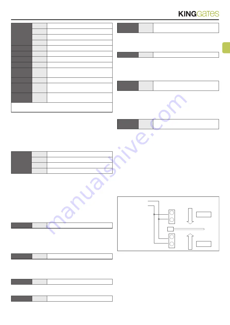
3.6 -
Two-way traffic light
The function of the traffic light in both directions is mainly to control
the flow of traffic in both directions as they go across the controlled
road barrier.
A different command is placed for opening in both directions: Step
by Step for entering and Step by Step 2 (Open) for leaving; two traffic
lights are installed with the indications Red and Green, connected to
the Bar Open Indicator and Courtesy Light outputs.
TRAFFIC LIGHT
Bulbs Max 5W
BAR OPEN
INDICATOR (9)
COUR
ESY LIGHT (8)
V
R
CONTROL WITH:
STEP BY STEP 2
ENTER
EXIT
V
R
CONTROL WITH:
STEP BY STEP
4
The two outputs are usually off and so are the two traffic lights; when
a command is given with Step by Step to enter, movement is started
and the Bar Open Indicator output is activated: this means there will
be a green light to enter and a red light to leave.
But should the command be given with the Step by Step 2, the Cour-
tesy Light output will be activated and there will be a green light to
leave and a red light to enter.
Summary of Contents for STAR OPEN 4000
Page 2: ......


