8” JOINTER ASSEMBLY
ASSEMBLING CUTTERHEAD GUARD
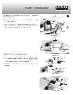
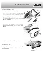
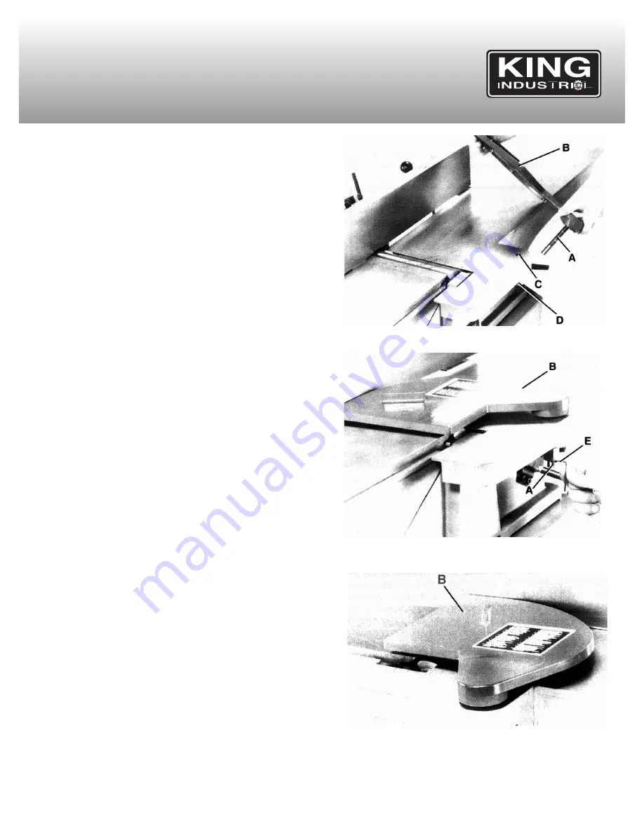
1. Remove set screw (not shown) from post (A) Fig. 14, of cutterhead
guard (B).
2. Insert post (A) Fig. 14, through hole (C)
in the infeed table.
NOTE:
A spring is supplied in knob assembly (D) Fig. 14, that returns the
guard (B) over the cutterhead after a cut has been made. Turn knob (D)
to provide tension on the spring inside knob assembly (D) Fig. 14,
engages inside the slot of the post. If spring tension is too much, or too
little that it does not allow the cutterhead guard to spring back over
the cutterhead, adjust the spring tension as necessary by removing the
guard and rotating knob (D).
3. Thread set screw (E) Fig. 15, which was removed in
STEP 1,
back
into post (A) to keep cutterhead guard (B) in position during
operation.
4. Fig. 16 illustrates the cutterhead guard (B) assembled to the jointer.
ASSEMBLING DUST CHUTE
The jointer has a built-in dust chute to expel sawdust efficiently during
cuts. If you will be connecting a dust collection system to the jointer, a
dust collector connector is supplied and can be fastened to the jointer
stand with four screws.
FIGURE 14
FIGURE 15
FIGURE 16

