assEmblY of THE aIR compREssoR
Your compressor requires minor assembly.
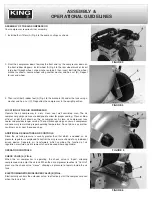
1. Install both air filters (A) Fig.3 to the pump castings as shown.
2. Pivot the compressor down towards the front and lay the compressor down on
the front rubber stoppers. Install wheel (A) Fig.4 to the rear wheel bracket. Insert
large bolt through wheel, slide washer onto bolt, then insert bolt into the wheel
bracket as shown, secure wheel using another washer and hex. nut (B). Repeat
for second wheel.
3. Then install both rubber feet (A) Fig.5 to the brackets (B) under the tank using a
washer and hex. nut (C). Reposition the compressor in the upright position.
locaTIon of THE aIR compREssoR
Operate the air compressor in a dry, clean, cool, well ventilated area. The air
compressor pump and case are designed to allow for proper cooling. Clean or blow
off dust or dirt that collects on the air compressor. A clean air compressor runs
cooler and provides longer service. The ventilation openings on your air compressor
are necessary to maintain proper operating temperature. Do not place rags or other
containers on or near these openings.
aDDITIonal REgUlaToRs anD conTRols
Since the air tank pressure is usually greater than that which is needed, an air
pressure regulator is employed to control the air pressure ahead of any individual
driven device. Seperate air transformers which combine the function of air
regulation, moisture and dirt removal should be used where applicable.
opERaTIon conTRols
cHEck ValVE (a) fIg.6.
When the air compressor is operating, the check valve is “open”, allowing
compressed air to enter the air tank. When the air compressor reaches its “Cut-Out”
pressure, the check valve “closes”, allowing air pressure to remain inside the air
tank.
ElEcTRomagnETIsm UnloaDER ValVE (b) fIg.6.
Electronically controls the unloader valve, to effectively start the compressor even
when the tank is full.
assEmblY &
opERaTIonal gUIDElInEs
fIgURE 3
fIgURE 4
fIgURE 5
fIgURE 6


