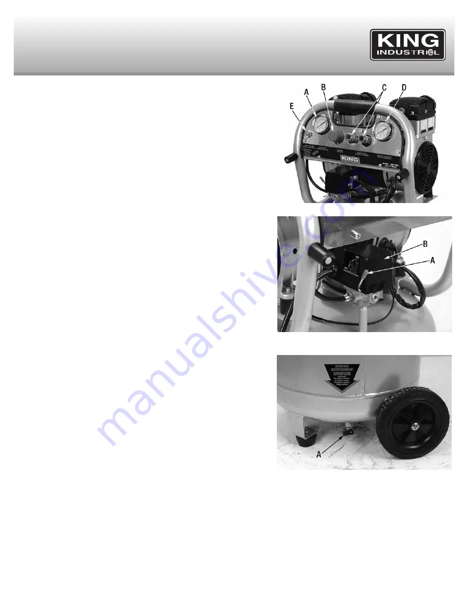
Tank pREssURE gaUgE (a) fIg.7.
The tank pressure gauge indicates the
reserve air pressure in the tank.
REgUlaToR (b) fIg.7.
The air pressure coming from the air tank is controlled by
the regulator. Turn the regulator knob clockwise to increase pressure or
counterclockwise to decrease pressure.
DUal “onE ToUcH” 1/4” QUIck RElEasE coUplERs (c) fIg.7.
Connect an
air hose with a 1/4” male coupler installed and connect it to one of the two female
quick release couplers.
oUTlET pREssURE gaUgE (D) fIg.7.
The outlet pressure gauge indicates the
air pressure available at the outlet side of the regulator. The pressure is controlled
by the regulator and is always less than or equal to the tank pressure.
asmE safETY ValVE (E) fIg.7.
If the pressure switch does not shut off the air
compressor at its cutout pressure setting, the safety valve will protect against high
pressure by “popping out” at its factory set pressure (slightly higher than the pressure
switch cut-out setting).
WaRnIng!
: If the safety valve does not work properly, over pressurization may
occur, causing air tank rupture or an explosion. Daily pull the ring on the safety valve
to make sure that the safety valve operates freely. If the valve is stuck or does not
operate smoothly, it must be replaced with the same ASME type of valve.
on/aUTo-off sWITcH (a) fIg.8.
Turn this switch ON to provide power to the
automatic pressure switch and OFF to remove power at the end of each use.
pREssURE sWITcH (b) fIg.8.
The pressure switch automatically starts the motor
when the tank pressure drops below the factory set “Cut-In” pressure. It also stops
the motor when the air tank pressure reaches the factory set “Cut-Out” pressure.
DRaIn ValVE (a) fIg.9.
The drain valve is located at the base of the air tank and
is used to drain condensation at the end of each use. Turn drain valve counterclock-
wise to open (no pressure build-up) or clockwise to close it (permits pressure build-
up).
preparation for use:
1. Before attaching an air hose or accessories, make sure the On/Off switch (A) Fig.8
is set to “OFF” and the air regulator (B) Fig.7 is closed (completely turned
counterclockwise).
WaRnIng
: Too much air pressure causes a hazardous risk of bursting. Check the
manufacturer's maximum pressure rating for air tools and accessories. The regulator
outlet pressure must never exceed the maximum pressure rating of the tool being
used.
2. Turn the switch (A) Fig.8 to the On position and allow tank pressure to build. Motor
will stop when tank pressure reaches “cut-out” pressure.
3. Open the regulator (B) Fig.7 by turning it clockwise. Adjust the regulator to the
correct pressure setting. The compressor is ready for use.
opERaTIonal gUIDElInEs
& opERaTIon
fIgURE 7
fIgURE 8
fIgURE 9

