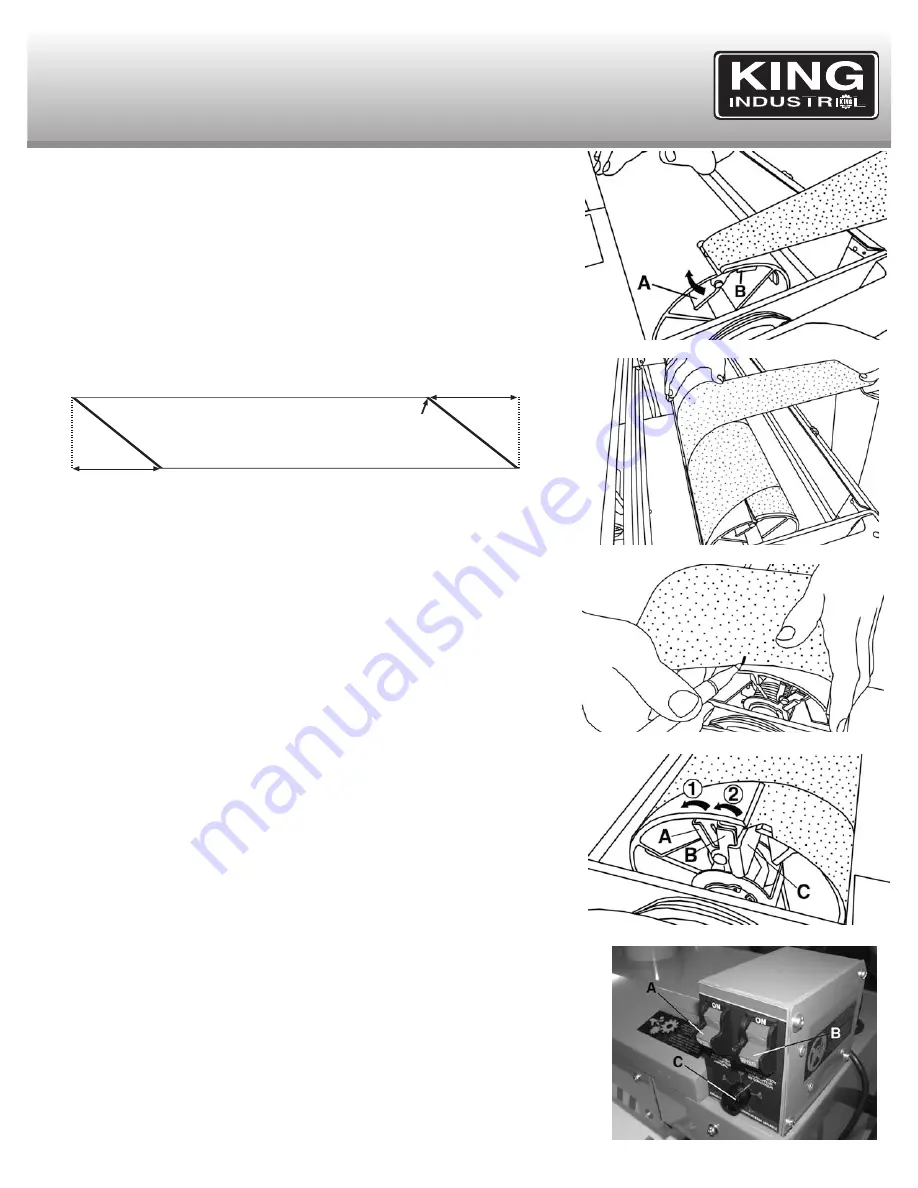
Removing the sanding belt
WARNING! MAKE SURE THAT THE MACHINE IS DISCONNECTED FROM THE
POWER SOURCE BEFORE REMOVING OR INSTALLING A SANDING BELT!
In order to access the sanding drum, unlatch and lift the sanding drum cover. The sanding
belt is held in place at both ends of the drum by a spring loaded clamp (left side) and a
spring loaded clamp with tensionner (right side). Apply finger pressure on these spring
loaded clamps and pull the sanding belt out of them.
IMPORTANT: BEFORE DOING ANY SANDING, WE RECOMMEND REMOVING THE
SANDING BELT FROM THE SANDING DRUM TO MAKE A PATTERN AS REFERENCE
FOR FUTURE REPLACEMENT SANDING BELTS.
Unwind the old sanding belt and use it as a pattern or use the pattern in the illustration
below to cut the new 3-1/4” x 96” (approx.) sanding belt, it is necessary to cut a triangular
portion of the sanding belt at each end using the dimensions below.
Installing sanding belt
Pull the left spring loaded clamp lever (A) Fig.12 forward to allow the “L” end of the
sanding belt tab (see illustration above) to slide under the clamp (B). Release the clamp to
lock the belt tab into place. Refer to Fig.12 as reference, this figure shows the proper
starting position of the sanding belt.
Roll the sanding belt onto the drum, keeping the edges snug as shown in Fig.13. A small
gap inbetween the sanding belt is fine but overlapping is not good.
Once the edge of the sanding belt reaches the right edge of the drum, make a mark on the
edge of the sanding belt as shown in Fig.14. Unwind, unclamp and remove the sanding belt
from the drum. Using the mark on the sanding belt as reference, cut the triangular portion
away as shown in illustration above and repeat the installation procedure.
Once you have reinstalled the sanding belt and have reached the right side of the drum,
push the spring loaded clamp lever and tensionner assembly (A & B) Fig.15 backwards to
allow the “R” end of the sanding belt tab (see illustration above) to slide under the clamp
(C). In order to clamp and tension the sanding belt, first release the clamp lever to clamp
the sanding belt tab, finally release the entire tensionner assembly to tension the sanding belt.
Drum sander controls
Important note: The conveyor motor and the sanding drum motor operate independently
from each other. The On/Off switch with removable safety key (A) Fig.16 activates and
stops the sanding drum and a separate On/Off switch with removable safety key (B)
activates and stops the variable speed conveyor belt. The variable speed adjustment dial
(C) sets the conveyor feed speed.
Note: Always start the dust collector before turning on the drum sander.
To turn the machine on, lift the switch with removable safety key (A) to the “On” position to
start the sanding drum. Lift the conveyor belt switch with removable safety key (B) to the
“On” position to start the conveyor belt feed. Both these switches come with a removable
safety key that allows each switch to be locked in the “Off” position. To activate the locking
feature, lower switch to the “Off” position and pull the safety key out of the switch. To
reactivate the switch, simply reposition the safety key in the switch. Set the conveyor belt
feed speed using the variable speed adjustment dial (C). Turning dial clockwise will
increase the conveyor belt speed.
When the operation is done, lower both the conveyor belt On/Off switch and the sanding
drum On/Off switch to the “Off” position to stop the conveyor belt and sanding drum motor.
Figure 12
REPLACING SANDING BELT
& OPERATION
Figure 13
Figure 14
Figure 15
15-3/4”
15-3/4”
Grit side of sanding belt
L
R
Mark
Figure 16


