MOUNTING AND
BREAK-IN PROCEDURES
MOUNTING
Warning! This compressor is not intended for outdoor installation. Never use
the transport skid for mounting purposes.
Make sure you mount the air compressor in a clean, well ventilated area
where the surrounding air temperature will not exceed 40
0
celcius. Position
the air compressor about 18 inches away from any wall. Make sure there is
sufficient space to access the tank drain cock.
Floor mounting
This air compressor is extremely top heavy. Before operating, the air
compressor feet (3) MUST be bolted to a flat, even, concrete floor. It is
recommended to purchase rubber pads (not included) to absorb vibrations.
A flexible coupling (not included) should be installed between the ball valve
and piping.
*IMPORTANT BREAK-IN PROCEDURES*
NOTE: SERIOUS DAMAGE MAY RESULT IF THE FOLLOWING BREAK-
IN INSTRUCTIONS ARE NOT CLOSELY
FOLLOWED. THESE
PROCEDURES ARE REQUIRED BEFORE THE AIR COMPRESSOR CAN
BE PUT INTO SERVICE, AFTER REPLACING THE CHECK VALVE, AND
WHEN A PISTON OR A CYLINDER SLEEVE ARE REPLACED.
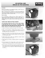
1) Make sure the pressure switch lever (A) Fig.3 is in the “OFF” position.
2) Make sure the compressor is properly wired to electrical source and
grounded, if a power cord was installed, plug the power cord into a
grounded 240V branch circuit receptacle.
3) Make sure the oil level in the crankcase reaches the centre dot of the oil
sight glass (A) Fig.4, refer to maintenance section for instructions on how
to fill the crankcase with oil.
4) Open the drain valve (A) Fig.5, turn it clockwise as shown, this will
prevent air pressure build-up in the tank.
5) Move the pressure switch lever (A) Fig.6 to “ON/AUTO”. The compressor
will start.
6) Run the compressor for 15 minutes. Make sure the drain valve is open
and there is no tank pressure build-up (tank pressure gauge at zero).
7) After 15 minutes, close the drain valve by turning it counterclockwise. The
air receiver will fill tank to cut-out pressure and the motor then will stop.
The air compressor is now ready for use. Proceed to the following “Piping”
instructions.
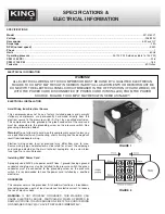
FIGURE 3
FIGURE 4
FIGURE 5
FIGURE 6

