background image

IMPORTANT INFORMATION

1-YEAR 

LIMITED WARRANTY 

FOR THIS 20” PLANER 

KING CANADA TOOLS

OFFERS A 1-YEAR LIMITED WARANTY 

FOR INDUSTRIAL USE.

PROOF OF PURCHASE

Please keep your dated proof of purchase for warranty and servicing purposes.

PARTS DIAGRAM & PARTS LISTS

Refer to the Parts section of the King Canada web site for the most updated parts diagram and parts list.

REPLACEMENT PARTS

Replacement parts for this tool are available at our authorized KING CANADA service centers across Canada. For servicing, contact

or return to the retailer where you purchased your product along with your proof of purchase. Please use the 10 digit part numbers listed

in this manual for all part orders where applicable.

LIMITED TOOL WARRANTY

KING CANADA makes every effort to ensure that this product meets high quality and durability standards. KING CANADA warrants to

the original retail consumer a 1-year limited warranty as of the date the product was purchased at retail and that each product is free

from defects in materials. Warranty does not apply to defects due directly or indirectly to misuse, abuse, negligence or  accidents,

repairs or alterations and lack of maintenance. KING CANADA shall in no event be liable for death, injuries to persons or property or

for incidental, special or consequential damages arising from the use of our products. To take advantage of this warranty, the product

or part must be returned for examination by the retailer. Shipping and handling charges may apply. If a defect is found, KING CANADA

will either repair or replace the product.

KING CANADA TOOLS INC. DORVAL, qUEbEC, CANADA H9P 2Y4

Summary of Contents for KC-520C

Page 1: ...INSTRUCTION MANUAL MODEL KC 520C COPYRIGHT 2002 ALL RIGHTS RESERVED BY KING CANADA TOOLS INC 20 INDUSTRIAL PLANER ...

Page 2: ...IMITED TOOL WARRANTY KING CANADA makes every effort to ensure that this product meets high quality and durability standards KING CANADA warrants to the original retail consumer a 1 year limited warranty as of the date the product was purchased at retail and that each product is free from defects in materials Warranty does not apply to defects due directly or indirectly to misuse abuse negligence o...

Page 3: ...is clean and not slippery due to wax and sawdust build up 6 AVOID DANGEROUS ENVIRONMENT Don t use power tools in damp or wet locations or expose them to rain Keep work area well lit and provide adequate sur rounding work space 7 KEEP CHILDREN AWAY All visitors should be kept a safe distance from work area 8 MAKE WORKSHOP CHILD PROOF Use padlocks master switches or remove starter keys 9 USE PROPER ...

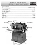
Page 4: ...head Number of knives 4 Diameter 3 15 Speed 5 000 RPM Cuts per minute 20 000 Feed Rolls Spiral Infeed Diameter 2 Table bed rolls Adjustable Table 25 7 x 20 01 TECHNICAL INFORMATION GETTING TO KNOW YOUR PLANER Gear Box Cover Elevation Handwheel Rear Extension Table Depth Scale Speed Change Knob Locking Nuts 1 of 4 Columns Enclosed stand Base Table rollers Belt Housing Cover Lifting handle Front Ext...

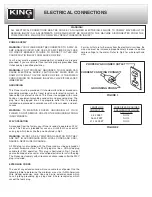
Page 5: ...AINTAIN PROPER GROUNDING OF YOUR PLANER DO NOT REMOVE OR ALTER THE GROUNDING PRONG IN ANY MANNER 220V OPERATION As received from the factory your Planer is ready to operate on 220V circuit This Planer is intended for use on a circuit that has an outlet and a plug which looks like the one illustrated in Fig 1 WARNING DO NOT USE A TWO PRONG ADAPTOR FOR THEY ARE NOT IN ACCORDANCE WITH LOCAL CODES AND...

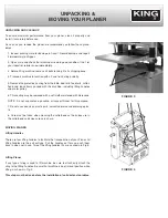
Page 6: ...g handles and motor pulley 6 This coating may be removed with a soft cloth moistened with Kerosene NOTE Do not use acetone gasoline or lacquer thinner for this purpose 7 Do not use solvents on plastic parts solvents dissolve and dammage plas tic 8 Care must be taken when cleaning the cutterhead as the knives are in the cutterhead and knives are very sharp MOVING PLANER Lifting Handles There are fo...

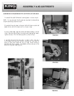
Page 7: ...shown in Fig 6 3 Using a staight edge align the motor and cutterhead pulleys as shown in Fig 7 the motor plate B Fig 5 can be moved for alignment by loosen ing the set screws C in the motor plate B as shown in Fig 5 4 Assemble the belts to the two pulleys as shown in Fig 7 and adjust for the proper belt tension by raising or lowering the motor plate as shown in Fig 8 then tighten the nuts A Fig 8 ...

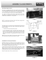
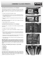
Page 8: ... 11 across both rollers loosen the screws B Fig 11 and turn the eccentric shafts C to raise or lower the table rollers when the proper height is obtained tighten screws B The table rollers must be adjusted on the opposite end of the table in the same manner NOTE Be sure that the height of the front and rear rollers are the same The table rollers must always be set parallel to the table ASSEMbLING ...

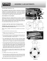
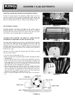
Page 9: ...fe gauge A Fig 16 and check all four knives Knives should just contact the bottom of the center protru sion B of the knife gauge as shown in Fig 16 4 If an adjustment to one or more of the knives is necessary slightly loosen the knife locking bars C Fig 16 of all four knives by turning the 24 locking screws D Fig 16 into the knife locking bars just enough to relieve stress in the cutterhead and no...

Page 10: ...e bolt A and loosen bolt B Fig 19 these two bolts will allow you to move the idler sprocket assembly C far enough to release tension on the chain as shown in Fig 20 4 Remove chain from the sprocket from the corner which needs adjusting Fig 20 shows the chain removed from the sprocket D 5 Turn sprocket D by hand to bring that corner into adjustement with the other three corners IMPORTANT NOTE Turni...

Page 11: ...own in Fig 24 If an adjustment to the infeed roller chipbreaker pressure bar or outfeed roller is necessary follow the next steps Example To check and adjust the outfeed roller 0 02 below the cutting circle proceed as follows 1 Disconnect Planer from power source 2 Make sure the knives are adjusted properly before attempting the follow ing adjustment 3 Place the gauge block G on the table directly...

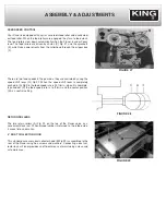
Page 12: ...ft lever G Fig 27 When the speed shift lever is completely pushed in A Fig 28 the feed speed rate is 20 ft min when it is complete ly pulled out C the feed speed rate is 16 ft min and the center position B is a neutral setting RETURN ROLLERS The two return rollers A Fig 29 on the top of the Planer serve as a convenient stock rest When planed lumber is returned to the infeed side it saves time and ...

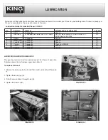
Page 13: ...e 32 8 Bushing Frequently SAE 30 31 FIGURE 30 FIGURE 31 FIGURE 32 LUbRICATION GUIDE FOR GEAR bOX The gear box lubricant must be replaced every 2 500 hours of operation Suitable lubricant is multi purpose gear box lubricant To replace lubricant 1 Remove the drain plug A Fig 30 and filter cap B drain dirty oil thorough ly 2 Tighten the drain plug A 3 Fill with clean lubricant through hole B 4 Tighte...

Reviews: