OPERATIONAL GUIDELINES
& MAINTENANCE
OPERATIONAL GUIDELINES
Factory Pressure Setting & Adjustment
This compressor comes with a factory operating pressure setting of 95-125 PSI
(cut-in and cut-out), the cut-out pressure setting may be increased up to 150 PSI
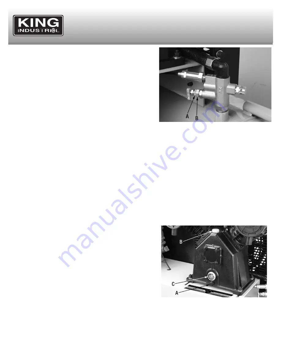
by making an adjustment to the load master valve assembly Fig.11.
Caution!
We strongly recommend keeping the cut-out pressure setting between
125-135 PSI. Exceeding this pressure will put additional strain on the engine and
pump and may cause the safety valve to occasionally “pop”.
To increase the cut-out pressure setting, using a wrench, loosen the load
master valve (A) Fig.11 by turning it counterclockwise. Then turn the load
master valve fitting (B) clockwise. Make small adjustments at first and test the
new setting until the desired cut-out pressure setting is obtained. Retighten the
load master valve.
Moisture in compressed air
When humidity is high or when the compressor is in continuous use for an extended period of time, this moisture will collect in the air tanks.
When using a spray gun or sandblast gun, this water will be carried from the tank through the hose and out of the gun as droplets mixed with
the spray material. This will cause water spots in a paint job, especially when spraying other than water based paint. If sandblasting, it will cause
the material to cake and clog the gun, rendering it ineffective. An optional air control unit with dirt and moisture removal should be used to
prevent these undesirable results.
MAINTENANCE
Before doing any maintenance or adjustments to your air compressor, the following safety precautions should be taken:
- Turn engine off and drain air tanks of pressure.
After Use:
1) Turn engine off.
2) Pull ring on safety valve (E) Fig.8, allowing air to bleed from the tanks until tank pressure is approximately 20 PSI. Release safety valve ring.
3) Drain moisture/water from air tanks. Open drain valves (A & B) Fig.9, turn them counterclockwise to open.
WARNING!
: Water will condense in the air tanks. If not drained water will corrode and weaken the air tanks causing a risk of air tank rupture.
NOTE:
If a drain valve is plugged, pull ring on safety valve (E) Fig.8, and hold until all air pressure has been released. The valve can then be
removed, cleaned, and reinstalled.
4) After the water has been completely drained, turn drain valves clockwise to close.
Daily or before each use
1) Check pump oil level. Oil level must be in the centre of the red dot of oil sight
glass.
2) Drain condensation from tank.
3) Check for any unusual noise or vibration.
4) Be sure all nuts and bolts are tight.
Monthly
1) Inspect air system for leaks by applying soapy water to all joints. Tighten those
joints if leakage is observed.
Initial pump oil change must be done after the first 100 hours
1) Once initial pump oil change is done after 100 hours of operation, change
pump oil every 300 hours or 6 months, which ever comes first. See changing
oil instructions.
2) Replace oil more often if used near paint spraying operations or in dusty
environments.
CHANGING OIL
To change oil, oil must be drained from the crankcase by removing oil drain bolt (A) Fig.12. Drain oil and replace oil drain bolt. To fill the
crankcase with oil, first unscrew and remove oil fill cap (B), pour air compressor oil (approx. 900ml of SAE 30 weight non-detergent oil) into oil
opening until the oil level reaches the red dot at the centre of the oil sight glass (C). Reinstall the fill cap (B).
KEEP COMPRESSOR CLEAN
Periodically blow out all air passages with dry compressed air. Clean all parts with a soft damp cloth.
CAUTION
: Wear safety glasses while
using compressed air.
FIGURE 12
FIGURE 11


