AsseMbly
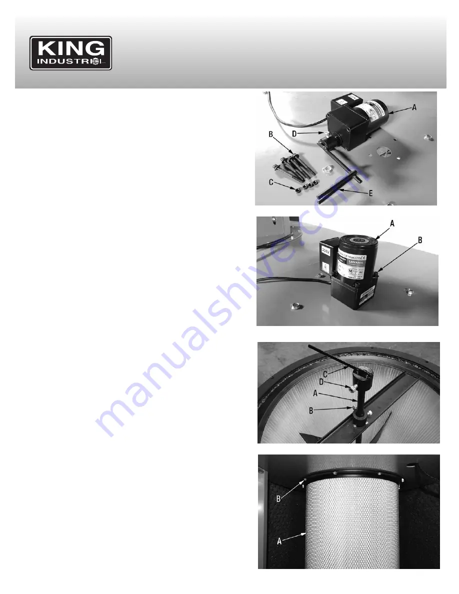
12. Now the auto-clean motor assembly (A) Fig.8 must be installed to the top
of the isolation panel, inside the opening shown in Fig.8.
13. Undo and remove the 4 cap screws (B) and hex. nuts (C) which secure the
two halves of the motor assembly. Remove cap screw (D) from the fork
assembly (E).
14. Insert the fork assembly (E) Fig.8 into the opening on the top of the
isolation panel. Position the auto-clean motor (A) Fig.9 as shown. Secure
the auto-clean motor to the isolation panel using the 4 cap screws (B) and
hex. nuts (C) Fig.8 removed previously. The help of a second person to
secure motor is recommended.
15. Reinstall the cap screw (D) Fig.8 on the fork assembly (E) from under the
isolation panel.
16. Install the canister filter shaft (A) Fig.10 on the small canister filter shaft,
tighten cap screws (B). Make sure one cap screw is tightened against the
flat of the canister filter shaft.
17. Next install the auto-clean shaft (C) on canister filter shaft (A), tighten cap
screw (D). Make sure cap screw is tightened against the flat of the
auto-clean shaft.
18. This Cyclone Dust Collector comes with an auto-clean motor function
which automatically turns the canister filter paddles to dislodge dust.
Before attempting to install the canister filter, it is extremely important that
the auto-clean shaft (C) Fig.10 get positioned in between the fork
assembly (E) Fig.8. With the help of another person, position the canister
filter (A) Fig.11 under the main impeller housing and the isolation panel,
line up the auto-clean shaft and the fork assembly and raise the canister
filter up against the main impellor housing. Secure canister filter using 10
flange head hex. bolts (B) Fig.11.
FIgure 8
FIgure 9
FIgure 10
FIgure 11


