asseMblY & adJUstMents
installing a sanding spindle or drUM
1. Make sure the spindle sander is disconnected from the power source.
2. Select the desired sanding spindle or sanding drum to install.
3. Clean the threaded shaft of the spindle or drum and the oscillating spindle open-
ing before mounting.
4. Screw the threaded shaft of the sanding spindle or sanding drum in the counter-
clockwise direction by hand into the oscillating spindle.
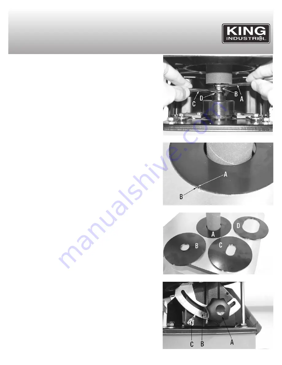
5. Place the supplied 17mm open end wrench (A) Fig.7 on the flat of the
threaded shaft (B). At the same time, place another 17mm open-end wrench (C)
on the flat of the oscillating spindle seat (D). Turn both open end wrenches to-
wards each other to secure the sanding spindle or sanding drum.
6. Do not over tighten, this could make it very difficult to remove the sanding spindle
or sanding drum after use.
installing tHe appropriate table insert
FAILURE TO USE THE PROPER INSERT WITH THE CORRESPONDING SPIN-
DLE MAY RESULT IN INJURY AND/OR DAMAGE TO THE MACHINE OR THE
WORKPIECE.
1. This machine comes 4 table inserts. When changing spindles, the table insert
will need to be changed to the matching size. Each table insert has a notch (A)
Fig.8 to fit the alignment pin (B) in the table to ensure that it is properly fitted and
installed in the table opening.
2. There are 2 table inserts with round openings (A & B) Fig.9 and 2 with oblong
openings (C & D). The oblong table inserts are used when the table is tilted for
bevel sanding.
Using tHe appropriate table insert
SPINDLE/DRUM DIAMETER
TABLE INSERT (SHAPES)
1/4” ..................................................ROUND & OBLONG -SMALL (B & C) Fig.9
1/2” ..................................................ROUND & OBLONG -SMALL (B & C) Fig.9
5/8” ..................................................ROUND & OBLONG -SMALL (B & C) Fig.9
1-1/2” ..............................................ROUND & OBLONG -LARGE (A & D) Fig.9
2” ....................................................ROUND & OBLONG -LARGE (A & D) Fig.9
tilting tHe table Up to 45
0
1. Loosen the two table lock knobs (A) Fig.10, located under the table on both
sides of the sander.
2. Tilt the table forward to the desired angle with your hands.
3. An angle scale (B) and pointer (C) are provided at the right side of the trunnion
to indicate the degree of table tilt.
4. Tighten the two table lock knobs securely after the table degree has been ad-
justed.
FigUre 7
FigUre 8
FigUre 9
FigUre 10


