Technical parameter and complete vehicle description
P-A-1
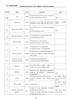
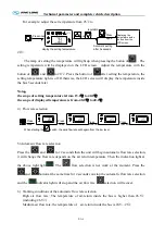
For example: adjust the set temperature from 25 to
℃
20
℃
A U T O
2 5
Press once
and
regulation
Press
again
display the setting temperature
Automatic setting
after 5 seconds
Displaying the
temperature inside
the bus from the
LCD screen
The lamp of setting the temperature will light up when pressing the button of
. The
setting temperature will be displayed on the LCD screen. Adjust the temperature with the
button of
and
to 20 . Press the button of
℃
after setting the temperature, the
setting temperature light is off. Otherwise, the LCD screen will display the temperature inside
the bus 5 seconds later.
Note
:
the scope of setting temperature is from 15.0
to 40.0
℃
℃
the scope of displayed temperature is from -40.0
to 40.0
℃
℃
4)
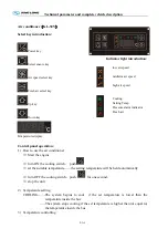
Flow rate selection
℃
25
25
℃
When starting the switch, the wind flowrate will begain from the low level .
→
Press
four times
→
Press
three times
→
Press
twice
Press
once
→
℃
25
O
25
℃
5) Automatic flow rate selection
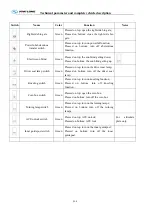
Press the
and
for 2 seconds then the unit will begin automatic flow rate selection,
it will change the flow rate depends on the air return temperature. Then the indication light at
the above right light
. The
flow selection is not work at the moment. Press the
and
button at the same time for 2 seconds can stop the automatic flow rate selection
and the
indicator light will stop and the air flow rate
selection will recover.
6)
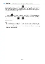
Working conditions of the automatic flow rate selection
High air flow rate: The temperature of air-return inside the bus is higher than 26.5
℃
(including 26.5 ).
℃
Medium air flow rate: the temperature of air-return inside the bus is 24.5—26 .
℃
Summary of Contents for XMQ6120C series
Page 36: ...Technical parameter and complete vehicle description 0 K 1 Lock1 Lock 2 Lock 3 ...
Page 133: ...Appendix A 4 Air braking schematic diagram ...
Page 134: ...Appendix A 4 Electric schematic diagram of the complete vehicle 1 ...
Page 135: ...Appendix A 5 Electric schematic diagram of the complete vehicle 2 ...
Page 136: ...Appendix A 5 Electric schematic diagram of the complete vehicle 3 ...
Page 137: ...Appendix A 5 Electric schematic diagram of the complete vehicle 4 ...

