Technical parameter and complete vehicle description
P-A-3
11)
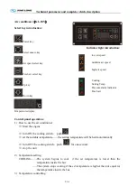
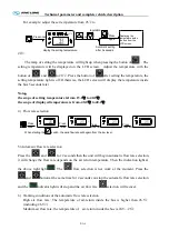
The part below the LCD screen will flash when the defrosting function working.
D is p la y t h e d e f r o s t in g t e m p e r a t u r e
2 5 . 5 .
A U T O
Note
:
The compressor (COMP) and the condenser (C
⑴
OND) fan will stop working and
the evaporate (EVA) fan will run normally when the system defrosting.
The operation of the defrosting is automatically Controlled. the defrosting operation
⑵
begins to work when the temperature of the sensor is(ON) at -1
a
℃
nd stops working
(OFF) at 8
.
℃
12)
Set the fresh air vent function
The LCD screen
will display the Vent open (Vn) and the
setting time when the button
pressed for 5 seconds. The button pressed again to show
VF and the setting time. Adjust the setting time by pressing the button of
and
to
the setting time within 1—60min.
(
Generally the setting time is 10 minutes
)
. Press the button
for the confirming of the time setting, or the system will confirm the setting time
automatically in 5 seconds. Adjust the setting time by the button
and
within
1—60min when the LCD screen display VF and the setting time.
(
Generally the setting time is
30 minutes
)
. Press the button
for the confirming of the time setting or the system will
confirm the setting time automatically after 5 seconds.
Note
:
Restart the (VENT) switch to carry out the new procedures after the setting.
Otherwise, the previous setting will be carried out again.
Only one parameter can be set for each time.
13). check the power.
Press the
10 seconds, it shows the air conditioner voltage. Press the
, it shows the
Summary of Contents for XMQ6120C series
Page 36: ...Technical parameter and complete vehicle description 0 K 1 Lock1 Lock 2 Lock 3 ...
Page 133: ...Appendix A 4 Air braking schematic diagram ...
Page 134: ...Appendix A 4 Electric schematic diagram of the complete vehicle 1 ...
Page 135: ...Appendix A 5 Electric schematic diagram of the complete vehicle 2 ...
Page 136: ...Appendix A 5 Electric schematic diagram of the complete vehicle 3 ...
Page 137: ...Appendix A 5 Electric schematic diagram of the complete vehicle 4 ...

