background image

Vehicle Starting and Driving 

S-17 

5. Check emergency devices and driver’s tools 
 

Such as extinguisher, crosstie for blocking vehicle, emergency hammer, jack and etc.. 
 

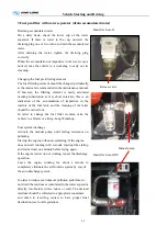
Fire extinguisher: 
 

The pulse super-micro powder fire extinguisher is fixed 
in the engine compartment, when the compartment is on 
fire, the fire extinguisher activate automatically or is 
active by manual work to eradicate the fire


The fire button is usually located at auxiliary instrument 
desk in the driver compartment where people could 
operate it easily.


Operation

1. When the engine compartment caught fire, 

the driver should stop vehicle and switch off engine 
immediately, open the fire button cover, and press the 
fire button, start-up fire extinguisher


2.Fire extinguisher may start-up automatically when   
it catches fire or its temperature arrives at 

170

.


Important hint: 

1. Fire extinguisher can be used for one time only, 
  DO NOT press the fire button except for   

emergency condition.   


2. The fire extinguisher can not start–up by press the 
  fire button manually if the vehicle battery is dead or   

power turn off. 

 
3. If the vehicle needs to be repaired, you could take   

away the anode and the cathode. And put them back   
after the reparation completed. 


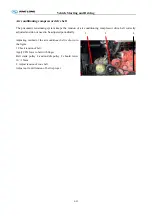
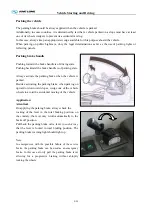
Inner fire extinguisher is fixed under the passenger’s 
chair, when vehicle caught fire, stop vehicle and use the 
fire extinguisher.


Fire extinguisher 

Fire button 

Summary of Contents for XMQ6120C series

Page 1: ... 1 OPERATION MANUAL User s Guide King Long XMQ6120C series tourist bus Xiamen King Long United Automotive Industry Co Ltd ...

Page 2: ... vehicle and thus the manufacturer Xiamen King Long United Automotive Industry Co Ltd will not takes the responsibility for the damages caused by them Any problem in service please contact our special maintenance network or after sales department We will ensure timely and complete maintenance as well as original parts supply In order to satisfy all kinds of different demand of the consumers we str...

Page 3: ... instruction I 1 7 Illustration of switch and indicator s SI 1 6 Air conditioner control panel P A 1 Pre heater panel P H 1 2 Gearbox operation O G 2 3 Open or close the passenger door O K 1 2 Adjustment of the driver s seat OI 1 Horn button OI 2 Adjustment of the steering wheel OI 3 Ignition switch OI 4 Lamplight operating handles OI 5 Wiper operating handle OI 6 Retarder operation O R 1 Passenge...

Page 4: ...rasion and pressure and tire nut for fixture S 13 Air cleaner S 14 General leakages water oil fluids and fuel S 15 Fastening and state of seat belts S 16 Check emergency devices and driver s tools fire extinguisher S 17 Windshield wipers and conditions of wiper blades and arms S 18 Electrical rearview mirror S 19 Power steering system S 20 Clutch actuation system fluid level S 21 General state and...

Page 5: ... filter M 4 Cleaning outside of radiator M 5 Coolant specification M 5 Oil specification recommendation of the fuel and the lubricant M 6 Breaking in of a new vehicle M 9 Daily or Refueling Maintenance Operation M 11 Maintenance first 2500km M 12 Maintenance per 5000km M 13 Maintenance per 10000km M 16 Maintenance per 20000km M 17 Maintenance per 40000km M 20 Maintenance per 80000km M 20 Maintenan...

Page 6: ... 14 Electrical equipment and the starting system C 16 Air conditioner system C 18 Appendix Driver s tool table A 1 Tightening moment of the bolts and the nuts in major position A 2 Air braking schematic diagram with air suspension A 4 Electrical elementary diagram of vehicle A 5 ...

Page 7: ...ition Wheelbase mm 6200 Wheel track Front mm 2080 Rear mm 1860 Minimum lift off clearance mm 150 Approach angle 9 departure angle 8 Front suspension rear suspension mm 2700 3300 Rated passenger driver included person 55 1 Mass parameter Kerb weight kg 12300 Max gross mass kg 18000 NO load Front axle kg 4600 Rear axle kg 7700 Full load Front axle kg 6500 Rear axle kg 11500 Wheel Tire size front rea...

Page 8: ... left lateral surface of the front wheel position of the main sill with vehicle identification number VIN on the frame Engine data plate The engine data plate is on top surface or salient top position of the engine whose position may be various according to different engine manufacturing plant The engine number is stamped on the left or right block of the engine whose position may be various accor...

Page 9: ...operation instruction or service manual Transmission operation manual CAN BUS Instrument system instruction book ABS anti braking system instruction book Air conditioner instruction book Heater instruction book Monitor instruction book VCD DVD instruction book Note the instruction book should be modified according to specific configuration of vehicle ...

Page 10: ...ee point safety belt step plate 7 Interior accessory device The vehicle is equipped with electronic clock sunshade safety hammer emergency escaping window curtain and luxury bilateral F 1 type luggage rack guiding seat reversal monitor Vehicle traveling data recorder reading lamp drinking trough guide mike etc 8 Air conditioning system Cooling system KINGLONG top mounted dependent air conditioning...

Page 11: ...icle may be different with the above description because of different deploying requirement of the clients Schematic illustration of the driver zone 1 WEBASTO Heating operation panel 2 Nanfeng radiator panel 3 A C control panel 4 VOITH gearbox operation panel 5 Parking brake hand lever 6 Charging socket 7 Wiper operation hand lever 8 Mirrors control button 9 Extinguisher press button 10 horn 11 St...

Page 12: ...arning see1 2 6 Right turning indicator When Right turning hazard switch is turned on 7 Retarder indicator Retarder work warning 8 Parking brake 9 DTCO warning communication error or without drivers card 10 Engine Revolution speed too high Need to change the gear or slow down the bus 11 Trip distance reset button Set trip distance to 0 12 LCD illumination adjust button Press the button to adjust t...

Page 13: ... open toilet water level low steering oil level low steering oil pressure low fuel level low DM1 error light error communication error 2 LCD Display Press the page switch button the pages will be displayed by the following sequence Detailed description is listed as below 2 3 Driving Information When the bus is running this page will show Figure 1 Figure 1 driving information pictogram comments pic...

Page 14: ...icate charging error if this symbol still exist after engine starts Coolant temperature high 98 C The bar shows brake circuit 1 pressure Coolant level low The bar shows brake circuit 2 pressure Rear flap open can not start the engine The bar shows engine oil pressure Worn brake shoes The bar shows SCR remain Hammer not at right position Function description 2 3 1 Transmission gear Display current ...

Page 15: ...uits 2 refers to the rear brake system pressure The symbol becomes red if the pressure is too low or if sensor is open load 2 3 7 Door status green means door is open yellow means the cap on the emergency switch is open either inside or outside brown means the knob in the emergency switch is moving 2 3 8 ECAS status ECAS lift kneeling ECAS general error ECAS severe error 2 3 9 Service request Pass...

Page 16: ...r fog light brake light turning light Other Error brake circuit pressure open load fuel sensor open load Engine cabin too hot worn brake shoes 1 6 fuel level low water in toilet level low air filter block 2 3 DM1 Diagnosis Information Figure 3 DM1 display page This page will show when some ECU sends out DM1 message The diagnosed ECU must support CAN diagnosis and provides SPN FMI code Line1 the ob...

Page 17: ... mode off Set temp the temperature currently set to be Room temp the real ambient temperature in the bus Outer temp outside temperature Evap_speed OFF High Mid Low Fan_speed OFF High Low 2 5 Engine Cabin Temperature high warning page If engine cabin temperature is higher than 85 C this page will appear automatically The temperature will show on the page The driver need to press the page change but...

Page 18: ...on I 7 2 6 Beeper warning conditions Brake circuit 1 pressure low Brake circuit 2 pressure low Coolant level low Hammer not at right position Engine cabin temperature high Oil pressure low after engine running Service request Left turning Right turning ...

Page 19: ...witch it on the whole vehicle lamps light Luggage compartment lamp Green Pressed on top lamp lights Pressed on bottom lamp goes out Compulsory radiator Green Pressed on top radiator working Pressed on bottom to turn it off only use this button when vehicle is stopping Ventilator Green Pressed on top ventilator is active Pressed on bottom ventilator is turned off Front fog lamp Green Pressed on top...

Page 20: ...tom TV is turned OFF Reversal monitor Green Pressed on top reversal monitor turned ON Pressed on bottom reversal monitories turned OFF Rearview mirror defrost preheating Yellow Pressed on top preheating ON Pressed on bottom preheating OFF Diagnose Green press this button to make a diagnosis of engine when engine indicate trouble Disinfect Green Pressed on top disinfection turned ON Pressed on bott...

Page 21: ...OFF Heater switch Red Pressed on top to turn on heater Pressed on bottom to turn it off TV overturn switch Green Pressed on top expand the TV Pressed on bottom collapse the TV Fresh air switch Green Pressed on top turn on the changing fresh air function Pressed on bottom turn off the changing fresh air function Electric driver window switch Green Pressed on top the glass getting up Pressed on bott...

Page 22: ...seat lamp switch Green Pressed on top turn on the driver seat lamp Pressed on bottom turn off the driver seat lamp Kneeling switch Green Pressed on top turn on kneeling function Pressed on bottom turn off kneeling function Coin box switch Green Pressed on top open the coin box Pressed on bottom turn off the coin box Turning lamp switch Green Pressed on top turn on the turning lamps Pressed on bott...

Page 23: ...ger door open indicate Red rear passenger door open indicating Red exit has been open indicating hollow plate Yellow ECAS alarm indicating Red ECAS fault indicating Red gearbox fault warning indicating Green retarder indicating yellow Fuel filter seeper Hollow plate Yellow Maintain waiting yellow Start Red Stop Yellow Alarm Red Water level hollow plate Green WC Red Service ...

Page 24: ...r and complete vehicle description SI 6 Indicator lamp Color Function Red Transmission oil temperature too high Red Transmission fault White Start up waiting Yellow Over emission Yellow Kneeling lamp Green Normal height ...

Page 25: ...e unit 2 Temperature setting COOLING The system begins to cool if the set temperature is lower than the temperature inside the bus The system stops cooling if the set temperature is higher than or equal to the temperature inside the bus 3 Temperature controlling Indicator light introduction low air speed midterm air speed high air speed Cooling Setting Temp Pressure alarm indicator Fresh air Selec...

Page 26: ...0 the scope of displayed temperature is from 40 0 to 40 0 4 Flow rate selection 25 25 When starting the switch the wind flowrate will begain from the low level Press four times Press three times Press twice Press once 25 O 25 5 Automatic flow rate selection Press the and for 2 seconds then the unit will begin automatic flow rate selection it will change the flow rate depends on the air return temp...

Page 27: ...onds when it s at the first starting after this the interval time is 30 seconds Temperature cycle2 C C Setting temperature25 C 25 C OFF cooling mode 27 C C on cooling mode 8 Strong cooling This function of maintenance is used in the season which the air conditioner does not use over 2 inside of bus The goal is provide the lubricant to the shaft sealing ring by the pressure of the working compresso...

Page 28: ...tton pressed again to show VF and the setting time Adjust the setting time by pressing the button of and to the setting time within 1 60min Generally the setting time is 10 minutes Press the button for the confirming of the time setting or the system will confirm the setting time automatically in 5 seconds Adjust the setting time by the button and within 1 60min when the LCD screen display VF and ...

Page 29: ...ds 14 check and cleanup time Press the for 12 seconds it shows the working time of air conditioner During this procss it isn t operation After 5 seconds it shows the air return inlet temperature When the air conditioner is working press the and for 2 seconds at the same time It can be cleanup the time as 0 Note the working time of air conditioner it can be calculated the time as hours since the lo...

Page 30: ...for more than 2 seconds the fast time setting mode is activated If the ignition is switched off while the heater is operating in the continuous mode the remaining operating time of 15 minutes is displayed and the heater continues to operate for this period of time 3 Switch the heater on Manually by pressing the button 8 continuous heating mode Automatically by programming the heater starting time ...

Page 31: ...e 9 and 10 buttons The remaining operating time refers to the time the heater still continues to remain in operation and the ignition switched off 11 Setting the wakeup time A wakeup time can only be programmed on the standard digital timer The wakeup time is not bound to a specific day of the week Repeatedly press the 7 button until the bell symbol appears on the display Set the desired wakeup ti...

Page 32: ...ton Driving forward If your vehicle is equipped with a safeguard against inadvertent gear engagement this facility must be operated first For that purpose step onto the brake pedal Press button D while the vehicle is at standstill and the engine idling When the brake is released now the bus will start moving Note If the vehicle fails to move off possible reasons may be the accelerator was actuated...

Page 33: ...g with buttons 1 2 or 3 pressed will increase fuel consumption Breaking With the DIWA transmission breaking is free of wear Actuating the brake pedal or the manual switch for converter brake will apply the converter brake Depressing the brake pedal further will apply the service brake Please note when braking on a slippery road the converter brake only acts on the driven wheels On vehicles without...

Page 34: ...ndstill Conditions for activation of ANS accelerator in idling position brake signal driving speed below 1 km h forward gear selected The power flow between engine and transmission is interrupted This results in fuel savings Reversing Press button R while the vehicle is at standstill and the engine idling and if available the reverse gear inhibiter button A change from Forward to Reverse or viceve...

Page 35: ...ndle 4 follow press the button 2 after that the door would be opened Specification For the king long city bus the method of open and close the passage door is different to above Details please see the right drawing The red button is close button the green button is open button This device usually located on the bin under the driver seat compartment If need open or close the front passage door with...

Page 36: ...Technical parameter and complete vehicle description 0 K 1 Lock1 Lock 2 Lock 3 ...

Page 37: ... upside of the door The model 3 door emergency switch is located inside the door pump cover which is on the top of the door Please rotate the switch and throw open the door in emergency Special attention The door emergency switch is only used in the emergency mode Please don t rotate the door emergency switch in driving for fear of danger Door remote controller 1 Door remote controller 2 Model 1 M...

Page 38: ...ell as the backrest angle according to requirement of the driver Handle 1 and Handle 2 cushion angle adjustment Handle 3 back and forth adjustment Handle 4 adjustment of the driver s weight Left handle backrest angle adjustment Note Number of handles varies with vehicle model Attention The seat should not be adjusted during driving to ensure driving safety 1 2 3 4 ...

Page 39: ... 0I 2 Horn button It is on the steering wheel The horn is hooting when pressing the button 1 The type of steering wheel may vary with vehicle model Please use the horn only when strictly necessary to warn other drivers and pedestrians Model 1 Model 2 1 1 ...

Page 40: ...ination of the steering wheel to the desired position After adjusting press the regulating handle or button down to lock the steering column Note Number of handles varies with vehicle model Attention Adjust the steering wheel only when the vehicle is stopped and the parking brake is on After adjusting press the regulating handle or button down in order to lock the steering column 1 2 ...

Page 41: ... idle speed If the vehicle does not move increase the fuel to the throttle modestly to increase the rotational speed of the engine a little this will also prevent the early wear and tear of the engine Allow the engine to run at idle speed for three to five minutes before turning it off Note 1 Turn the ignition key to the OFF position after the engine has been turned off and has stopped running 2 I...

Page 42: ...isely rotating the handle to position of this identification Is the Is the headlamp indication The headlamp small lamp meter lamp and width lamp will all be turned on when continuously clockwise rotating the handle to position of this identification Is the turning indication By back and forth motions of the operating handle may control the left and right turning lamp and that on the dashboard Is d...

Page 43: ...ering wheel model 4 Rotary handle 0 Out of work J interval wiper operation step 1 low speed wiper operation step 2 HI high speed wiper operation step The wiper may spray water by pressing the end of the handle The wiper may spray water by pressing the end of the handle The shifts of the retarder may be converted by back and forth motion of the handle Note do not actuate the wiper without water pre...

Page 44: ...ehicle description OI 8 Passenger control panel instruction 1 air outlet 2 service button 3 reading lamp button 4 lamp 5 loudhailer 6 stop button Model 1 Model 2 1 2 3 4 1 2 5 4 Model 4 1 2 3 4 Model 5 Model 6 1 2 6 4 5 4 2 1 3 Model 3 ...

Page 45: ...le description OI 9 Safety hatch The safety hatch is located on scaffold of the vehicle Please open the safety hatch according to the above diagrammatic representation and illustration for escaping in case of danger Model 1 Model 2 Model 3 ...

Page 46: ...er and complete vehicle description OI 10 Safety hammer The safety hammer is located on the side window Please take down the safety hammer and break open the safety window for escaping in case of danger Model 1 Model 2 ...

Page 47: ... Central control electric box installed the step wall behind of driver seat 2 Body module 1 installed the step wall behind of driver seat front control unit 3 Body module 2 installed in the air duct over the RH FR passenger seats ceiling control unit Installation position ...

Page 48: ... Body module 3 4 installed in cabin box at the RH RR middle rear control unit 5 Retarder control unit installed the step wall behind of driver seat 6 WABCO ABS control unit installed on the wall of luggage cabin 7 Instrument control unit installed in dash board ...

Page 49: ...s in our vehicle It collects input signals of digital and analog and to control the electric devices lights etc Part C Name WABCO ABS ECU Function description ECU receive and deal with the signal from the ABS sensor then transmit to ABS magnetic valve ABS magnetic valve control the brake pressure by this signal Part D Name DC DC convertor Function description Change the whole vehicle voltage 24V i...

Page 50: ...tion 0 E 2 relay ACC electric power relay air condition relay and four UPL system s relay Their names have been marked on the wire The capacity and the name of fuses also could be found on the fuse box cover or the King Long Instrument Wiring Harness ...

Page 51: ...Technical parameter and complete vehicle description 0 E 3 Switch control box Model CQ2025 CQ2025 A wiring diagram Printed on opposite cover of the switch control box ...

Page 52: ...nd complete vehicle description 0 E 4 The fan angle transmission mechanism This system has two benefits first it reduces transmission noise and second it improves cooling efficiency and requires only one belt instead of two ...

Page 53: ...en the engine compartment hood Take out the oil dipstick and clean it with a clean cloth without loose threads and put it back into its place fitting it in completely Once again pull out the dipstick and check the oil level a The oil should not exceed the maximum level drain the excess b If the oil is at operational level do not add more oil to the crankcase c If the oil is at or below the minimum...

Page 54: ...the system up until the maximum level indication Only use coolant which is recommended c The compensation tank cover should not be opened when temperature of the coolant is still high to avoid being scalded Place the lid on the system and turn it to the limit d Pressure valve of the compensation tank should be opened when adding the coolant to eliminate air in coolant pipeline of the diesel engine...

Page 55: ...terior of the fuel tank and the cleaning of the latter should be carried out In order to change the fuel filter element take the vehicle to a Dealer or a King Long Workshop Fuel system discharge Activate the manual pump until feeling resistance on pumping Start up the engine without accelerating If the engine does not start running in 20 seconds interrupt the startup and wait at least one minute b...

Page 56: ...n time and check fuel pipe for no leakage Ensure sealing performance of fuel tank and before opening fuel tank wipe up clay and dirt Before filling up shut down engine Do not drive vehicle to empty tank When the level indicator is on the red bar refuel the vehicle to avoid air from entering the fuel system Fill the tank only with good quality fuel free of contaminants The fuel might as well be fil...

Page 57: ...f the lenses and the quantity of lanterns for each type of vehicle The King Long vehicles leave the factory in strict obeyance of these specifications Traffic safety depends on these factors therefore do not change the place of the lanterns Substitute the damaged lanterns only for other original ones Remember that a change of lantern colors can confuse other motorists and result in serious acciden...

Page 58: ...dBlue If the remain volume of AdBlue is less than 6 this lamp will light and the power of engine will be declined forcibly This will cause the emission substandard and it is not good to engine 2 The daily maintenance of SCR system Please add the AdBlue when it is insufficiency Ensure the AdBlue meet the requirement Check the SCR system is well enough and has no leaking before driving There is obvi...

Page 59: ...f the AdBlue spill in skin mild irritation may occur Wash off with soap and water If the AdBlue spill in eye irrigate eyes with large amount of water The AdBlue is Non combustible if heated water evaporates and ammonia will be released ...

Page 60: ...k Open the water drain valve of air tank to drain oily water fully If too much oily water is bled check to see if desiccant needs to be replaced in air drier This may be avoided when adopting the automatic drain valve but it should be checked every two weeks ...

Page 61: ...e driver information digital display If the oil pressure is too low the oil pressure is automatically shown on the combination instrument Indication of the oil gauge will show a high value after the cold start of the engine and then it should be kept within the range of 0 3 0 5Mpa 3 5kg cm2 along with the increment of the oil temperature as well as the normal engine speed ...

Page 62: ...e STOP warning light comes on in case of low brake pressure in the service brake or parking brake circuits Attention If the driver information indicator displays the warning brake pressure and the STOP warning light comes on with the engine running it will be an indication that the air pressure is excessively low Do not drive the vehicle if the air pressure gauge displays low air pressure in one o...

Page 63: ... speed to avoid engine operating in the danger range red zone When the exhaust brake is being operated on down grades select an adequate gearbox speed ratio to keep engine speed within efficient exhaust brake operation yellow Always avoid engine over revving red zone as engine operation in this speed range can end up the engine damage immediately or will seriously jeopardize its durability The yel...

Page 64: ... the engine at idle gear and straighten the front wheels forwards Turn the steering wheel alternatively to the right and to the left The steering play free movement of the steering wheel is measured on the perimeter of the steering wheel and should be between 20 and 30 mm A ...

Page 65: ...for some time the tires heat and in consequence of the heat the inflation pressure increases Never under any circumstance empty heated tires to reestablish the recommended inflation pressure The pressure difference between the assemble tires on the same axle should not be superior to 0 1 bar Wheel hubs Keep them always clean eliminating eventual mud or other dirt adherence Substitute the damaged a...

Page 66: ...ly press the dust discharge valve with your hand in order to incomplete the dust which possibly be caught in the internal part maintaining them clear At the same time check clip connecting rubber hose of air intake system with steel tube in case of dust entering air intake system due to looseness and decrease in engine life The air cleaner restriction is electronically controlled If the indication...

Page 67: ...iving S 15 3 General leakages water oil fluids and fuel Check the engine the transmission the driving axle the steering system the cooling system and the oil pipeline the air pipeline of the complete vehicle for their leakage ...

Page 68: ...at belts Check buckle of the safety belt of the driver seat for normal and ensure for its lockup under the following situations when fastening the safety belt The body dashes forward all of a sudden The vehicle makes an emergency braking or an abrupt acceleration ...

Page 69: ... should stop vehicle and switch off engine immediately open the fire button cover and press the fire button start up fire extinguisher 2 Fire extinguisher may start up automatically when it catches fire or its temperature arrives at 170 Important hint 1 Fire extinguisher can be used for one time only DO NOT press the fire button except for emergency condition 2 The fire extinguisher can not start ...

Page 70: ...e the windshield wipers when the windshield is dry Before activating the wipers push the head of the wiper lever inward to spray detergent onto the windshield Check surplus of detergent Stop vehicle on a flat road open side cover of instrument desk Container of detergent is located inside instrument desk If detergent is insufficient add Add the clean water into the tank for windshield washer There...

Page 71: ...tton Model 1 L adjusting left rearview mirror R adjusting right rearview mirror Mirror button push down the arrow headed button to adjust the mirror for 4 directions Model 2 L adjusting left rearview mirror R adjusting right rearview mirror Mirror button rotate the handle to adjust the mirror for 4 directions Model 2 Model 1 Model 3 ...

Page 72: ...draulic help however in this condition there will be more steering wheel play and the steering will become noticeably heavier Drive the vehicle very carefully and take it to an authorized King Long Dealer or Workshop to re establish the correct working order of the steering system Important In the case of damage to the hydraulic steering pump or of the total loss of fluid from the hydraulic system...

Page 73: ...ake fluid used in the clutch activating system from entering into contact with the vehicle s plastic components or painted surfaces In the case of spilling or accidental dripping immediately clean the affected surface with cold water to avoid damage to these components or to the vehicle paint The fluid level in the clutch activating system container should be between the maximum and minimum level ...

Page 74: ...er or Workshop Ventilator drive belts If it is necessary to replace the ventilator drive belts in emergency situations adjust their tension in such a way that upon pressing them with one s thumb in the middle of the distance between the pulleys a defection of approximately 20mm is observed Loosen fastening nut of intermediary pulley before turning the adjusting bolt After adjusting ventilator belt...

Page 75: ...ressor drive belt correctly adjusted and do not need to be adjusted periodically Adjusting method of the air conditioner belt is shown in the figure 1 Check tension of belt Apply 98N force to belt with finger Belt crank pulley 4 and middle pulley 2 should lower 10 15mm 2 Adjust tension of cone belt Adjust nut 1until tension of belt is proper 1 2 4 ...

Page 76: ... compartment of left or right rear side 1 battery 2 switch control box To access the battery open the switch control box panel After the vehicle has been parked for the day the main power switch should be turned off Cleaning Keep the batteries always externally clean and the air vent unobstructed Avoid battery contact with petroleum derived products Charge Do not allow batteries to maintain a char...

Page 77: ...turn the ignition key back to the off position and wait at least 2 minutes After engine start up the vehicle can be put immediately into operation Note a The engine should be running at low middle speed for 3 5 minutes on every day s first starting before the driving b Never race the engine without warming up During cold start increase engine speed slowly and do not make engine run at maximum spee...

Page 78: ...ling The shift should be switched to the neutral position and power supply shut down Please make necessary inspection of engine and then troubleshoot Cautions Cautions during the winter operation Please add long life coolant to cooling system After parking please exhaust water in air tank in time Before winter comes please check level of battery electrolyte specific gravity and voltage Water used ...

Page 79: ...te the back cover course end switch bar in the engine compartment Loosen the switches immediately the engine begins running When the engine is turned on by way of the start up switch in the engine compartment this switch should be used as a manual accelerator With the engine compartment cover open the start up by way of the ignition key is impossible Engine shut down Press the shut down switch STO...

Page 80: ... should not be released abruptly to impulse the starting when the vehicle is stuck in the mud or can not start on a spoil road The following problems should also be paid attention to during the driving If abnormal noise or odor occurs please stop vehicle to check Abrupt acceleration or emergency braking should be avoided as might Don t put foot on the clutch pedal during the driving Avoid engine o...

Page 81: ...rking state Always activate the parking brake when the vehicle is parked Besides activating the parking brake when parking on upward or downward slopes wedge one of the vehicle wheels to avoid the accidental moving of the vehicle Application Attention On applying the parking brake always check the locking of the lever in the total braking position on the contrary the lever may return automatically...

Page 82: ...mission and front rear axle please refer to relative users guide For use and maintenance of other parts of chassis if without special user s guide or maintenance period please refer to this manual for maintenance information Body maintenance 1 Keep body clean Timely clean should be made after daily running and don t scrape body with tool in order to avoid paint scratch and damage of roll covering ...

Page 83: ...cal system maintenance and service 1 When battery is charged by external power supply disconnect ECU control box to prevent outer high voltage damage ECU electric control unit 2 When vehicle needs to weld disconnect ECU Don t use multimeter to measure ECU control box 3 Monitor voltage stability of generator regularly 4 Parts dismantling must be carried out after electric has been shut off and shou...

Page 84: ...ent of the brake pedal free play Loosen locknut of brake pedal push rod and adjust adjusting nut and then measure the vertical distance from pedal free position to the position where pressing resistance increases apparently when depressing pedal The value should be between 8mm and 12mm After adjustment lock the locknut Bus cleaning Don t pollute the environment when washing vehicle at washing shop...

Page 85: ...ng the filter 1 Remove butterfly nut on cover cap and take down cover cap and then take out filter element 2 Clean interior of the cover and the housing with a clean and dry napery when cleaning the filter cartridge prevent the water from entering the air filter 3 Exclude dust in unloading valve 4 The filter element may be cleaned by hand or by tapping the end surface with a wood bar or blowed by ...

Page 86: ...o requirement resulting in poor engine cooling and grave damage to components 4 If don t comply with this requirement it may cause poor engine cooling and bad damage to components 5 Anti freeze and antirust solution mixture of glycol and water should be added to cooling system perennially to avoid sediment frost oxidation and increase boiling point Note When adding coolant please choose the same m...

Page 87: ...el oil Suitable for the zone where venture rate is 10 percent and minimum temperature is more than 5 C 4 No 20 light diesel oil Suitable for the zone where venture rate is 10 percent and minimum temperature is more than 14 C 5 No 35 light diesel oil Suitable for the zone where venture rate is 10 percent and minimum temperature is more than 29 C 6 Natural gas only apply to Natural Gas Vehicle use n...

Page 88: ... start so the ambient temperature of the engine starting is the main reference for selecting viscosity of the winter engine oil Selecting multifunctional engine oil may avoid oil changing caused by temperature fluctuation HINT Never add any additive to above engine oil and different kinds of oil should be avoided using at the same time oil mixture must be the same grade oil and it is recommended t...

Page 89: ...th different types otherwise it will affect the using effect The original brake fluid should be cleaned out before replacing the compound brake fluid Chassis grease Grease added in each part should use 2 lithium base lubricant suitable for temperature within the range of 30 120 Vehicle with centralized lubrication should use 0 lithium base lubricant Water tank coolant Long life anti freezing and a...

Page 90: ... level 7 Check whether tire pressure has meet requirement 8 Check and see if each transmission gear can engage properly Maintenance during breaking in period 1 Running on smooth and good road surface 2 Drive properly and engage the clutch smoothly Gear shifting smoothly and impact is not allowed Neutral gear sliding is forbidden while engine stop Emergency brake should occur as few as possible 3 S...

Page 91: ...d rear suspension carry out when full load 9 Check connections of chassis and driving system according to specified torques Tighten torques please refer to corresponding instructions 10 Check hydraulic system components of steering mechanism for fixing and tightness 11 Lubricate and maintain vehicle according to maintain items at 5 000km 12 Check complete vehicle for oil water and air leakage ...

Page 92: ...nutes Drive belt Check correct No across crack wear or material break off Crankcase breather tube Check Check the breather tube in cold winter cleanup the ice blocking Engine and Accessories Check No damage and crack Clutch Clutch pedal free stroke Check adjust Clutch release bearing clearance Free stroke 30 40 mm Clutch system Check Check if clutch separated completely connection stable and not s...

Page 93: ...missions as well as fillings during transmission break in for first 7500km only Transmission fix bolt Fasten Transmission air hole Check clean Air hole smooth Transmission and Accessories Check No leakage operation organization effective no abnormal sound wrong gear engagement Propeller shaft Transmission shaft cross shaft flex sleeve Lubricate Transmission shaft bolt and nut Check and fasten 7 7 ...

Page 94: ...N II above 10 use C 3 10W Fix bolts of each place Fasten Each fastening bolts not loosening steering arm not loosening steering wheel swift Ball head Lubricate Each turning ball head not loosening no clogging clearance normal ZF series Maintenance Free GX85 GX 100 ZJ 100C Change oil and filter core of oil tank For first 5000km only N32 which manufactured by Shanghai oil refining factory or ATF or ...

Page 95: ...e adjust it in time The air spring surface Check clean Clean the lubricant grease on the surface the dirt on the piston the abnormal things placed between the piston and air spring The air spring Check If there is leakage in the joints of the air springs and the top cover the air springs should be taken apart then check whether the edges of the air springs and the top cover or the tapered sealing ...

Page 96: ... 6MPa The brake nuts Inspect Inspect fastening of rear brake board s nut 7 7 9 m 150 180 Nm 9m above front 160 205 Nm rear 196 245 Nm The pipe and joint sealing Check Check brake pipe and joint sealing No leakage Chassis Fastening body and chassis connective bolts nuts Check The whole vehicle body butter nozzle Lubricate Grease nozzle complete and effective lubrication good Electrical equipment Th...

Page 97: ...tion Check No leakage Air compressor Check No air oil coolant leakage lock nut and bolt no loosen or damage No carbon deposit Brake system Check No leakage Propeller shaft fastening bolt Check and fasten Propeller shaft flange fastening bolts not loosening universal joint Check and fasten Universal joint each bearing no loosening or damage Front axle DF series Brake bottom board Check No loosening...

Page 98: ...core of oil tank N32 which manufactured by Shanghai oi refining factory or ATF or related products which produced IPS series 25 35 40 55 65 Change oil and filter core of oil tank Environment temperature 10 adopt CD leve 15W 40 oil Environment temperature 10 adopt No 8 hydraulic drive fluid Front axle Toe in of front wheel Check adjust Radial ply tire 0 2mm Rear axle DF FS series Final drive Fillin...

Page 99: ...s elasticity please adjust or change them The height Check adjust Charge the air springs and adjust to the design height then check the wheel base the height of the vehicle body and the two side wheels locations which are relative to the frame If it is necessary please adjust the height of the air springs and the length of the rod in order to arrive to the design request Brake system Brake pedal f...

Page 100: ...able no air leakage safety valve normal pressure at 8Mpa check air reservoir if with seeper replace air drier filter element Electrical equipment Front lamp horn meters and signal Check set complete and effective Wiper generator Check Effective Wiper connection rod Check adjust Reliable Whole vehicle wiring Check adjust complete reliable insulation good Air conditioner Air con passage and read lam...

Page 101: ...no abnormal abrasion bush not crack lubrication normal Maintenance operation and regulation every 80000km or 12 months depend on what occurs first Every 80000km include every 40000km maintenance operation System Item Operation Technical requirement Engine Thermostats Replace Fuel roughing filter Replace Cooling system Release clean add Radiator Check Radiator without leakage damage fouling Hose wi...

Page 102: ...0 A131 Oil change 150 000 km 3 years TE ML122RL Rear Axle A 132 New AV 132 Oil change 150 000 km 3 years TE ML 12TE Old model lubricant grease of shaft of wheel hub change include oil seal 250 000KM or 2 years RENOLIT LX PEP 2Rs36 04e ZF parts No 0671 190 122 Wheel bearings with individual mounts at the front and rear axles 500 000 km 2 years Compact bearings hub unit in the wheel heads at the fro...

Page 103: ...R I R I R I R Air filter element C C C C C C R C C C C C R C C C C Check adjust belt I I I I I I I I I I I I I I I I I Check adjust engine idle speed I I I I I I I I I I I I I I I I I Fixing every bolt and connection on engine I I I I I I I I I I I I I I I I I Checking seal of pipe connector I I I I I I I I I I I I I I I I I Coolant I I I I I I I I I I I I I I I I R Fuel system I I I I I I I I I I...

Page 104: ...I I Free stroke of clutch pedal I I I I I I I I I Clutch oil I I I I I I I I R Clutch cylinder stroke I I I I I I I I I Transmission Transmission if not leaking oil I I I I I I I I I I I I I I I I I Selector mechanism I I I I I I I I I I I I I I I I I Lubricant oil R I I I R I I I R Venthole C I I I C I I I C I I I C I I I C Propeller shaft Drive shaft connecting parts I I I I I I I I I I I I I I ...

Page 105: ... I I I I I Engine exhaust brake I I I I I ABS unit checking I I I Brake valve other valves I I I Axle Tire Tire steel ring I I I I I I I I I I I I I I I I I Checking fixing RR axle housing differential housing RR cover half shaft bolt nut I I I I I I I I I I I I I I I I I Lubricant steering main pin brake adjusting arm cam shaft I I I I I I I I I Fixing wheel nut I I I I I I I I I Tire transpositi...

Page 106: ... I I I I I Absorber working condition I I I Steel plate suspension bush I I I Left right steel plate suspension flexibility I I I Fixing suspension U type bolt I I I I I I I I I Valves function I I I Bracket lifting lug installation wearing state I I I Steering system Checking steering system working condition oil leakage I I I I I I I I I I I I I I I I I Steering wheel free stroke working conditi...

Page 107: ...25 30 35 40 45 50 55 60 65 70 75 80 Month 1 3 5 7 8 9 10 11 12 Electrical system All lights I I I I I I I I I Battery electrolyte surface connector I I I I I I I I I Wire box installation I I I I I I I I I I I I I I I I I All wires circuitry connectors I I I I I I I I I A C system pre heater system Air conditioner system refrigeration working condition I I I I I I I I I A C compressor belt rate of...

Page 108: ...kage in the fuel inlet pipe Clogging of the fuel supply pump filters and fix or replace 6 Insufficient fuel injection without fuel injection or low injection pressure 6 Check the injector atomization situations and replace a new one if it doesn t work 7 Starting system problems 7 Check the connection to be correct and reliable Incorrect terminals connection or bad contact Insufficient battery char...

Page 109: ...ludge in the back of turbine and compressor impellers Clean it 5 middle cooler mangle leave out 5 Check and replace it 6 Fuel line blocked or leaky 6 Check the seal of fuel line and fuel filter choking or replace screw on filter element 7 Poor atomization of injector 7 Check the inject pressure remove carbon adjust and repair 8 Incorrect distribution phase 8 Check and adjust the distribution timin...

Page 110: ...ton 4 Check and adjust the valve timing 5 The driving gear is abrased and get too large gap There is knocking sound at the timing gear box cover 5 Check the gear side clearance and change the gear or not according to the abrasion situations 6 Too big clearance between piston and cylinder and there is knocking sound at the cylinder wall 6 Change the piston and use the repairing cylinder liner Keep ...

Page 111: ...sembly 8 middle cooler damaged and leaked 8 Repair or replace it Exhaust with white and blue smoke Possible causes Remedies 1 Poor quality fuel and too much water in fuel 1 Replace the fuel 2 Too low coolant temperature 2 Check the working temperature of the thermostat replace it if necessary 3 Incorrect distribution 3 Check and adjust it 4 Too low Pressure 4 Check the working temperature of the t...

Page 112: ...high oil pressure Possible causes Remedies 1 Too low ambient temperature and too high oil viscosity 1 Use the required grade engine oil Operate at low speed after starting and then check it when the oil temperature is normal 2 Over flow valve clogged 2 Check and clean it Too high oil temperature and oil consumption Possible causes Remedies 1 Leakage in the exterior oil line 1 Check and repair it 2...

Page 113: ...line 3 Cllogging of the flywheel supporting bearing 4 Pressure spring distorted 5 Impurity in the clutch plate the pressure plate and the flywheel 6 Distortion or breakdown of the diaphragm spring 2 The clutch pedal is in normal operation but the pedal travel is too large 1 Too large of the clutch pedal pusher stroke 2 Abrasion of the pedal bushing the interlocking pin and the pin hole 3 Too large...

Page 114: ...that pushing the clutch cylinder 10 Improper adjustment of push rod on the clutch booster that pushing the clutch 11 Clutch master cylinder oil return port is blocked 12 Abrasion of the clutch plate 1 Correct or replace the parts 2 Clean or replace the parts 3 Replace the pressure spring 4 Replace and use the correct spring 5 Tighten blots to specified torque 6 Adjust free play of pedal 7 Check th...

Page 115: ...ler shaft sliding yoke assembled incorrectly 2 The propeller shaft is distortion or bending 3 The universal joint journal or the needle bearing has been worn out or damaged 4 The propeller shaft loose 5 The propeller shaft is imbalance 6 The intermediate supporting bearing is worn out or damaged 7 Bracket of the intermediate supporting bearing is loose or the rubber damp piece material is aging 1 ...

Page 116: ...ge 2 Use the lubrication of given grade The transmission gear is off the engaging position Transmission 1 Shift fork distorted or worn 2 Abrasion of lthe lockup ball or the ball on the gear shifter shaft 3 Breakdown or fatigue of the lock spring 4 Excessive clearance of the gear engagement 5 Excessive clearance along the gearing axial direction 6 Abrasion of the sliding bearing slipper or its end ...

Page 117: ... rear axle improper sound When the vehicle is running 1 Excessive clearance between the driving and the driven gear 2 Abrasion or damage of the bearing 3 Abrasion or damage of the gear 4 Too low oil level When running with inertance 1 Too small clearance between the driving and the driven gear 2 Abrasion or damage of the bearing 3 Incorrect gear engaging position 4 Too low oil level 1 Adjust the c...

Page 118: ...g due to malfunction of sealing ring 1 Adjust the pre tightening force 2 Intensify the lubrication or replace the grease 3 Clean and intensify the lubrication 4 Replace the sealing ring Front axle and steering system Fault symptom Possible cause Eliminating method Steering wheel shimmy 1 The steering system 1 Steering gear housing bolt or steering column supporting loose 2 Looseness of the steerin...

Page 119: ...There has fatigue and damage in the front plate spring 3 Bending of the front axle 4 Unsmooth of the braking 5 Looseness of the front hub bearing nut 6 Inequality of the tire pressure 7 Tires with different dimension applied 1 Check and adjust the front wheel alignment 2 Replace the faulted spring 3 Adjust or replace the front axle 4 Please refer to the chapter braking 5 Tighten to specified torqu...

Page 120: ...ricant to the given level 2 Replace the lubricant 3 Replace the ball stud 4 Overhaul and eliminate trouble 5 Measure the backpressure and repair or replace the pipeline in case of the set value exceeded 6 Measure the oil pressure and the flow volume disassemble and repair the hydraulic pump if the set value belowed 7 Bleed air and add oil 8 Disassemble and repair rotary valve 9 Disassemble and rep...

Page 121: ...Replace the faulted parts 4 Eliminate causes of the spring braking unreleased 5 Disassemble and clean the faulted parts 6 Disassemble and clean the braking valve and replace the faulted parts as needed There has abnormal sound when troddening the brake pedal 1 The clincher or the bolt is projected because of abrasion of the braking friction lining 2 Surface hardening of the friction lining 3 Deter...

Page 122: ...il cylinder cover and the rubber cap 7 Replace it 8 Tighten the U bolt The braking can t be applied under all conditions When compressed air pressure is normal 1 Too short of the brake valve travel 2 The camshaft doesn t rotate the bushing is lack of lubricant 3 Improper adjustment of the braking chamber pusher stroke 4 Improper sliding contact of the relay valve 5 Overheat or deterioration of the...

Page 123: ...method There has abnormal sound during the generator rotates 1 The belt is of over loose or excessive abrasion with the shaking during the running 2 Bearing failure or oversize clearance 3 Too much bearing clearance Adjust the belt and replace the bearing The charging indicator light doesn t go off during the running and the vehicle is difficult to start 1 The battery is lack of power 2 The genera...

Page 124: ...r contact of the ignition switch or socket loose 2 Unsteady connection of the relay device or the solenoid switch 3 Turnoff of the starter solenoid switch 4 Damage of the starting gear or the gear ring of starter 5 Malfunction of engage switch 6 Starter armature shaft bent 1 Clean and tighten 2 tighten it 3 Replace it 4 Repair the teeth or replace it 5 Found out the reason and eliminate it 6 Repla...

Page 125: ...no temperature difference between high and low pressure pipe Air conditioner system has serious leakage Check the system and find out the leakage and fill the enough refrigerant 3 The low pressure is nearly to zero or even the negative value The high pressure is lower than the normal value No refrigerate in the system The front or the rear part of the expansion valve has fog expansion valve blocke...

Page 126: ...e inspection glass looks yellow Too much water in the system desiccators reaching the saturation the frosting water blocked the expanding valve Change the desiccators and make the vacuum repeatedly and then re fill the refrigerant 6 The low pressure is much higher than the normal value and the high pressure is a little bit higher than the normal value Cold is in sufficient The condenser blower doe...

Page 127: ...or failure or connection problem 3 temperature control sensor installation position not good 4 temperature control switch defective 5 harness connection not reliable 6 Control panel defective 1 change the defrost sensor or connect the cable again 2 change the temperature control or connect the harness again 3 re install the temperature control into the correct position 4 change the temperature con...

Page 128: ...orator blower not working 1 relay not working 2 battery no charge 3 battery cable confected 4 air blower harness not connected well 5 harness connection not good 6 venting blower cable not connecting well 7 air blower or blower speed adjustable resistor failure 8 control panel out of work 1 change relay or repair or connect the relay connecting cable 2 change the battery or recharge 3 reconnect th...

Page 129: ...ive locknut 55mm 16 Combination wrench 30 36 Spare wheel lifter 22X550 17 S double box wrench 13x15 37 Wrench for drive axle drain plug 10x10 18 Adjustable wrench 8 38 Jack 16t J1601 19 Adjustable wrench 12 39 Special tool box 20 Cross head screwdriver 6 The tools above are the state when choose Dongfeng Dena axle when other axles are applied driver tools may vary as below name cancel number add A...

Page 130: ...245 Fixing bolt between driven gear and differential 588 686 Differential housing nut 216 275 Fixing bolt Front brake chamber bracket 59 79 Fixing bolt Front brake chamber 40 59 Fixing bolt Rear brake chamber 167 196 Fixing bolt retarder housing 128 157 Fixing bolt axle shaft 137 176 Drive gear bearing cap bolt 120 137 Rear axle oil level check plug 127 157 Lock bolt front shoe axle 49 69 U bolt f...

Page 131: ...7 1050 774 1480 1092 1774 1308 M30 1420 1047 2010 1482 2400 1770 Torques for bolts with metric fine threads Dimension of bolt Torques N m ft lb 8 8 10 9 12 9 M8 1 26 19 37 27 48 35 M10 1 25 52 38 76 56 88 65 M12 1 25 98 72 137 101 126 119 M12 1 5 93 69 127 94 152 112 M14 1 5 152 112 216 159 255 188 M16 1 5 225 166 318 235 383 282 M18 1 5 324 239 466 344 554 409 M20 1 5 461 340 628 463 775 572 M22 ...

Page 132: ...rature is low than 10 C please apply ATF DEXRON II D or ATF DEXRON III hydraulic fluid to steering gear when ambient temperature is higher than 10 C please apply C 3 10W hydraulic fluid C 3 10W grade oil can be used in most area all year generally C 3 30 grade oil can be used in moderate temperature area all year generally 3 Others Oil Site Oil used Nominate Clutch Synthesize grade oil Nominate to...

Page 133: ...Appendix A 4 Air braking schematic diagram ...

Page 134: ...Appendix A 4 Electric schematic diagram of the complete vehicle 1 ...

Page 135: ...Appendix A 5 Electric schematic diagram of the complete vehicle 2 ...

Page 136: ...Appendix A 5 Electric schematic diagram of the complete vehicle 3 ...

Page 137: ...Appendix A 5 Electric schematic diagram of the complete vehicle 4 ...

Reviews:

Related manuals for XMQ6120C series