Technical parameter and complete vehicle description
- 10 -
Body Structure
1. Structural style
Semi-integral body structure
2. Structure
The bodywork structure adopts closed girder construction of six major assembly parts, which are
combined welded by rectangle steel pipes with advantages of strong structural stiffness, torsion
resistance and bending resistance as well as relatively simple craftwork. Whole vehicle skeleton has
been fully electro-coating operated and anticorrosion treated to ensure steady adhesion of coating and
strong capacity of antirust and corrosion-proof.
3. Interior trim
The interior adopts flexible design and the floor adopts steel plate/wood block composite construction,
and covered with anti-slip and antifriction leather with favorable sound insulation value.
4. Windows
The front windshield is the hyperboloid triplex glass fixed by the gluing; the rear windshield is fixed by
harden glass; the
side windows are sealing style , which are all made of hardened glass. The driver’s
window is fixed with sliding window.
5. Baggage compartment
The baggage compartment adopts transverse run-through design, and they are all made of aluminum.
6. Seat
Driver’s seat: Q15-2 adjustable seat with high backrest and three-point belt
Passenger seats: 2+2 layout, KE-1 seats with armrest, foot pedal and transverse movement function ,
49+1+1, all seats are mounted by 3 points seat belt.
7. Interior accessory device
The vehicle is equipped with electronic clock, electric single pieces front windshield sunshade, driver
side sunshade, electric driver window, safety hammer, double emergency escaping windows, curtain
and luxury bilateral C type luggage rack , icebox, middle passenger door, toilet, combination reading
lamp, electric mirrors, DVD player, front and middle flip LCD TV ,reversal monitor , .etc.
8. Air-conditioning system
Cooling /heating A/C system: KING LONG top mounted dependent air-conditioning system,
WEBASTO heating system.
Defroster: cooling /heating defrosting device.
9. Door
The door adopts the full aluminum remote control out-swing single-wing pneumatic passenger doors.
The out-swing door adopts the advanced electrically aerodynamic theory design, with the motion of
opening and closing placidly
、
agilely
、
safely , further, keeping credible locking and anti-clamp
function.
A. Basic function
a. There are two electrically switches, the interior one is trigger touch-tone, which located on the
dashboard of the front right side of the driver, the outside one is a remote control switch. , both switches
can control the door.
b. When the circuit is in OFF position , the emergency switch can be used in the interior and exterior,
the emergency switch of the door is located inwardly upon the entrance of the door and outwardly under
of the door steps , Please rotate the switch and throw open the door in emergency.
c. Commonly the door is closed, when touch off any electrically switch, the door would move placidly
at a certain velocity, along with it, the step-lamp lights .when touch off the switch again , the door
would return placidly at a certain velocity, after the door returned , the step-lamp goes out.
Summary of Contents for XMQ6127 series
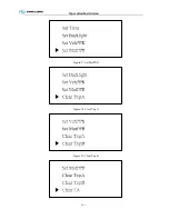
Page 18: ...Operation Instruction CI 1 Figure 17 Set MotPPR Figure 18 Clear Trip A Figure 19 Clear Trip B...
Page 32: ...Operation Instruction P A 1 2 Control panel operation...
Page 33: ...Operation Instruction P A 1...
Page 34: ...Operation Instruction P A 1...
Page 35: ...Operation Instruction P A 1...
Page 36: ...Operation Instruction P A 1...
Page 41: ...Operation Instruction 0 G 1 1 1 2 2 Pushbutton Settings...
Page 42: ...Operation Instruction 0 G 1 1 2 Starting the Engine 1 3 Selecting the Gear...
Page 43: ...Operation Instruction 0 G 1 1 4 Setting Off 1 5 Driving Ranges...
Page 44: ...Operation Instruction 0 G 1 1 5 1 Downhill Travel 1 5 2 Downhill Travel 1 5 3 Kickdown...
Page 46: ...Operation Instruction 0 G 1 1 6 Stopping Parking...
Page 51: ...Operation Instruction 0 G 1 1 11 1 Limp Home Mode 1 12 Auxiliary Control Unit...
Page 52: ...Operation Instruction 0 G 1 1 12 1 Operating Instructions for the Auxiliary Control Unit...
Page 53: ...Operation Instruction 0 AB 1 WABCO ABS BASIC INTRODUCTION...
Page 54: ...Operation Instruction 0 AB 1...
Page 55: ...Operation Instruction 0 AB 1...
Page 56: ...Operation Instruction 0 AB 1...
Page 57: ...Operation Instruction 0 AB 1...
Page 58: ...Operation Instruction 0 EC 1 ECAS System Introduction 1 System introduction...
Page 59: ...Operation Instruction 0 EC 1 3 System function...
Page 60: ...Operation Instruction 0 EC 1...
Page 77: ...Operation Instruction 0 E 1 CAN bus module...
Page 158: ...Appendix A 4 Air braking schematic diagram...
Page 159: ...A 5 Electric schematic diagram of the complete vehicle 1...
Page 160: ...A 6 Electric schematic diagram of the complete vehicle 2...
Page 161: ...A 7 Electric schematic diagram of the complete vehicle 3...
Page 162: ...A 8 Electric schematic diagram of the complete vehicle 4...

