Maintenance and service
M-4
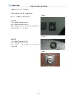
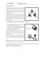
Cleaning the air filter
Hint:
Please replace filter element under such conditions:
it has been washed 5 times; filter element has been
damaged; filter element is clogged excessively; after
changing the engine oil .When air filter indicator on
combination instrument lights, clean the air filter or
replace the element.
Dirty air filter would lead to deficient power and engine
worn. In order to assure the life and normal operation of
engine, please perform periodic maintenance on air filter.
Check and maintain air filter every 2000km. Under some
conditions, such as heavy dust and etc., interval time
should be shortened.
The engine must be stalled during the air intake system
maintaining and the engine should not be started after withdrawing the filter.
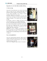
(1) Remove butterfly nut on cover cap and take down
cover cap and then take out filter element
(2) Clean interior of the cover and the housing with a clean
and dry napery. when cleaning the filter cartridge.
prevent the water from entering the air filter.
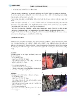
(3) Exclude dust in unloading valve.
(4) The filter element may be cleaned by hand or by
tapping the end surface with a wood bar or blowed by
compressed air . Also wash with lotion. But take care not
to break element.
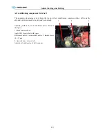
Blow with compressed air: blow the filter element from
inside to the outside with the dry compressed air of the
pressure not exceeding 5bar until there has no dust blown
out.
Caution:
Outside surface of the filter cartridge should be
cleaned with cloth instead of blown with compressed air.
Wet washing: Put filter element in lukewarm containing general cleaning agent and swing it and then clean
with fresh water and dry it after dehydration.
Hint:
Before wet washing, blow filter element clean.
Summary of Contents for XMQ6127 series
Page 18: ...Operation Instruction CI 1 Figure 17 Set MotPPR Figure 18 Clear Trip A Figure 19 Clear Trip B...
Page 32: ...Operation Instruction P A 1 2 Control panel operation...
Page 33: ...Operation Instruction P A 1...
Page 34: ...Operation Instruction P A 1...
Page 35: ...Operation Instruction P A 1...
Page 36: ...Operation Instruction P A 1...
Page 41: ...Operation Instruction 0 G 1 1 1 2 2 Pushbutton Settings...
Page 42: ...Operation Instruction 0 G 1 1 2 Starting the Engine 1 3 Selecting the Gear...
Page 43: ...Operation Instruction 0 G 1 1 4 Setting Off 1 5 Driving Ranges...
Page 44: ...Operation Instruction 0 G 1 1 5 1 Downhill Travel 1 5 2 Downhill Travel 1 5 3 Kickdown...
Page 46: ...Operation Instruction 0 G 1 1 6 Stopping Parking...
Page 51: ...Operation Instruction 0 G 1 1 11 1 Limp Home Mode 1 12 Auxiliary Control Unit...
Page 52: ...Operation Instruction 0 G 1 1 12 1 Operating Instructions for the Auxiliary Control Unit...
Page 53: ...Operation Instruction 0 AB 1 WABCO ABS BASIC INTRODUCTION...
Page 54: ...Operation Instruction 0 AB 1...
Page 55: ...Operation Instruction 0 AB 1...
Page 56: ...Operation Instruction 0 AB 1...
Page 57: ...Operation Instruction 0 AB 1...
Page 58: ...Operation Instruction 0 EC 1 ECAS System Introduction 1 System introduction...
Page 59: ...Operation Instruction 0 EC 1 3 System function...
Page 60: ...Operation Instruction 0 EC 1...
Page 77: ...Operation Instruction 0 E 1 CAN bus module...
Page 158: ...Appendix A 4 Air braking schematic diagram...
Page 159: ...A 5 Electric schematic diagram of the complete vehicle 1...
Page 160: ...A 6 Electric schematic diagram of the complete vehicle 2...
Page 161: ...A 7 Electric schematic diagram of the complete vehicle 3...
Page 162: ...A 8 Electric schematic diagram of the complete vehicle 4...


