Maintenance and service
M-5
Caution:
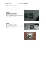
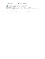
Vapor spray gun, solution, gasoline or equivalent should not be used during the cleaning.
-
Before reinstalling air filter element, check element from inside to outside with check lamp for
damage;
-
Check sealing ring for damage or cracks.
Caution:
Do not start the engine without mounting the air filter.
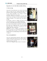
Clean outside of the radiator
Keep outside of radiator clean. Compressed air current can eliminate all the dirt blocking air flow.
For vehicle equipped with intercooler, please keep air radiator fin clean. If there is hard dirt in radiator
fin, blow fan side and then the other side with compressed vapor current. In order to avoid damage to
air radiator fin or water radiator fin, ensure spray of air, water or vapor perpendicular to radiator surface.
It should be sent to the king-long special maintenance station to make decontamination and final
disposal if there has much dirt in the water radiator and the air radiator.
1. Clean water radiator fin and air radiator fin termly and eliminate dirt blocking air flow, which is
important for ensuring the engine cooling.
2. For zone with many winged insect, please clean radiator fin frequently.
3. If users do not operate according to requirement, resulting in poor engine cooling and grave
damage to components.
4. If don’t comply with this requirement, it may cause poor engine cooling and bad damage to
components.
5. Anti-freeze and antirust solution (mixture of glycol and water) should be added to cooling system
perennially to avoid sediment, frost, oxidation and increase boiling point.
Note: When adding coolant, please choose the same model as much as possible in case of sediment. If
coolant is degenerative, replace it entirely and immediately.
6
.
Never use water to replace coolant for a long period.
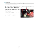
After long running of engine, scale will come into being in cooling system. It should be eliminated in
time. Methods as follows: mix 700-800g caustic soda with 150g kerosene and then inject the mixed
liquid into cooling water and make engine run at middle speed for 5-10 minutes. 10-12 hours later,
make engine run again for 10-15 minutes and then drain aqueous solution and clean cooling system
with clean water.
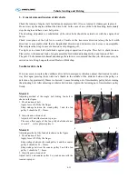
Charging-up the coolant
Anti-freeze and antirust solution (mixture of glycol and water) should be added to cooling system
perennially to avoid sediment, frost, oxidation and increase in boiling point.
NOTE:
When adding coolant, please choose the same brand as much as possible in case of sediment.
If coolant is degenerative, replace entirely.
After long operation of engine, please eliminate scale in cooling system in time. Methods as shown
Summary of Contents for XMQ6127 series
Page 18: ...Operation Instruction CI 1 Figure 17 Set MotPPR Figure 18 Clear Trip A Figure 19 Clear Trip B...
Page 32: ...Operation Instruction P A 1 2 Control panel operation...
Page 33: ...Operation Instruction P A 1...
Page 34: ...Operation Instruction P A 1...
Page 35: ...Operation Instruction P A 1...
Page 36: ...Operation Instruction P A 1...
Page 41: ...Operation Instruction 0 G 1 1 1 2 2 Pushbutton Settings...
Page 42: ...Operation Instruction 0 G 1 1 2 Starting the Engine 1 3 Selecting the Gear...
Page 43: ...Operation Instruction 0 G 1 1 4 Setting Off 1 5 Driving Ranges...
Page 44: ...Operation Instruction 0 G 1 1 5 1 Downhill Travel 1 5 2 Downhill Travel 1 5 3 Kickdown...
Page 46: ...Operation Instruction 0 G 1 1 6 Stopping Parking...
Page 51: ...Operation Instruction 0 G 1 1 11 1 Limp Home Mode 1 12 Auxiliary Control Unit...
Page 52: ...Operation Instruction 0 G 1 1 12 1 Operating Instructions for the Auxiliary Control Unit...
Page 53: ...Operation Instruction 0 AB 1 WABCO ABS BASIC INTRODUCTION...
Page 54: ...Operation Instruction 0 AB 1...
Page 55: ...Operation Instruction 0 AB 1...
Page 56: ...Operation Instruction 0 AB 1...
Page 57: ...Operation Instruction 0 AB 1...
Page 58: ...Operation Instruction 0 EC 1 ECAS System Introduction 1 System introduction...
Page 59: ...Operation Instruction 0 EC 1 3 System function...
Page 60: ...Operation Instruction 0 EC 1...
Page 77: ...Operation Instruction 0 E 1 CAN bus module...
Page 158: ...Appendix A 4 Air braking schematic diagram...
Page 159: ...A 5 Electric schematic diagram of the complete vehicle 1...
Page 160: ...A 6 Electric schematic diagram of the complete vehicle 2...
Page 161: ...A 7 Electric schematic diagram of the complete vehicle 3...
Page 162: ...A 8 Electric schematic diagram of the complete vehicle 4...

