Maintenance and service
M-12
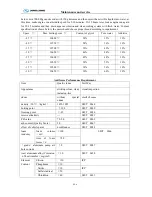
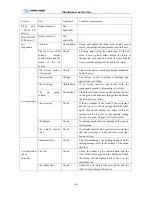
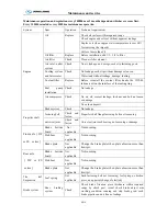
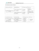
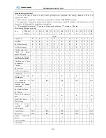
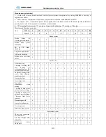
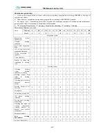
Daily Maintenance Operation
System Item
Operation Technical
requirement
Engine
Air cleaner
Check
No leakage, damage, and crack.
Clips without looseness.
Fuel-water
separator
Drain
Release the water and fouling
Cooling fan
Inspect
Do not pull or lever the cooling fan for starting the engine.
No crack, looseness, bend or damage.
air inlet/ outlet
piping
Maintenance
check
Pipes without wear and damage, clips without looseness
prevent the air leakage.
Coolant level
Check
Do not remove the water tank cover, unless the temperature i
less than 50
℃
, otherwise, it’s dangerous for operator
Do not add the cold coolant into the hot engine, unless the
engine temperature is less than 5
0℃
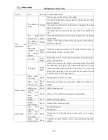
Engine oil level
Check / correct
Do not start engine when oil level less than “L” or more than
“H”.
Vehicle parking level, check the oil after engine stops for 5
minutes
Drive belt
Check / correct No across crack, wear or material break off
Crankcase
breather tube
Check
Check the breather tube in cold winter, cleanup the ice
blocking.
Engine and
Accessories
Check
No damage and crack
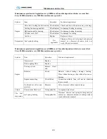
Clutch
Clutch pedal free
stroke
Not applicable
Clutch release bearing clearance
Free stroke: 30
~
40 mm
Clutch system
Not applicable
Check if clutch separated completely, connection stable and
not skidding
Clutch brake fluid
level
Not applicable
Compound brake fluid
Brake chambe
stroke
Not applicable
Air
suspension
Vehicle body
Check
Observe the vehicle body whether tilt or not, the air spring (o
piping) of one side is leaky if this side is lower.
The air springs
Check
If hear the sound of leaking obviously
,
we can deal with the
problem after confirming the specific leaky location
Training
1.Correct operation: no neutral speed skidding; no idle speed running of engine for a long time
2.Correct maintenance: replace oil, oil filter element, diesel filter element , transmission, axle, angle
transmission system periodically, clean and replace air filter element periodically
Summary of Contents for XMQ6127 series
Page 18: ...Operation Instruction CI 1 Figure 17 Set MotPPR Figure 18 Clear Trip A Figure 19 Clear Trip B...
Page 32: ...Operation Instruction P A 1 2 Control panel operation...
Page 33: ...Operation Instruction P A 1...
Page 34: ...Operation Instruction P A 1...
Page 35: ...Operation Instruction P A 1...
Page 36: ...Operation Instruction P A 1...
Page 41: ...Operation Instruction 0 G 1 1 1 2 2 Pushbutton Settings...
Page 42: ...Operation Instruction 0 G 1 1 2 Starting the Engine 1 3 Selecting the Gear...
Page 43: ...Operation Instruction 0 G 1 1 4 Setting Off 1 5 Driving Ranges...
Page 44: ...Operation Instruction 0 G 1 1 5 1 Downhill Travel 1 5 2 Downhill Travel 1 5 3 Kickdown...
Page 46: ...Operation Instruction 0 G 1 1 6 Stopping Parking...
Page 51: ...Operation Instruction 0 G 1 1 11 1 Limp Home Mode 1 12 Auxiliary Control Unit...
Page 52: ...Operation Instruction 0 G 1 1 12 1 Operating Instructions for the Auxiliary Control Unit...
Page 53: ...Operation Instruction 0 AB 1 WABCO ABS BASIC INTRODUCTION...
Page 54: ...Operation Instruction 0 AB 1...
Page 55: ...Operation Instruction 0 AB 1...
Page 56: ...Operation Instruction 0 AB 1...
Page 57: ...Operation Instruction 0 AB 1...
Page 58: ...Operation Instruction 0 EC 1 ECAS System Introduction 1 System introduction...
Page 59: ...Operation Instruction 0 EC 1 3 System function...
Page 60: ...Operation Instruction 0 EC 1...
Page 77: ...Operation Instruction 0 E 1 CAN bus module...
Page 158: ...Appendix A 4 Air braking schematic diagram...
Page 159: ...A 5 Electric schematic diagram of the complete vehicle 1...
Page 160: ...A 6 Electric schematic diagram of the complete vehicle 2...
Page 161: ...A 7 Electric schematic diagram of the complete vehicle 3...
Page 162: ...A 8 Electric schematic diagram of the complete vehicle 4...

