Maintenance and service
M-16
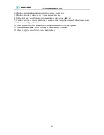
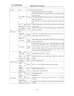
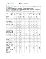
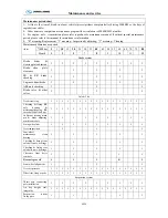
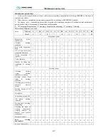
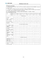
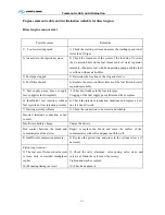
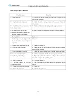
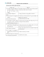
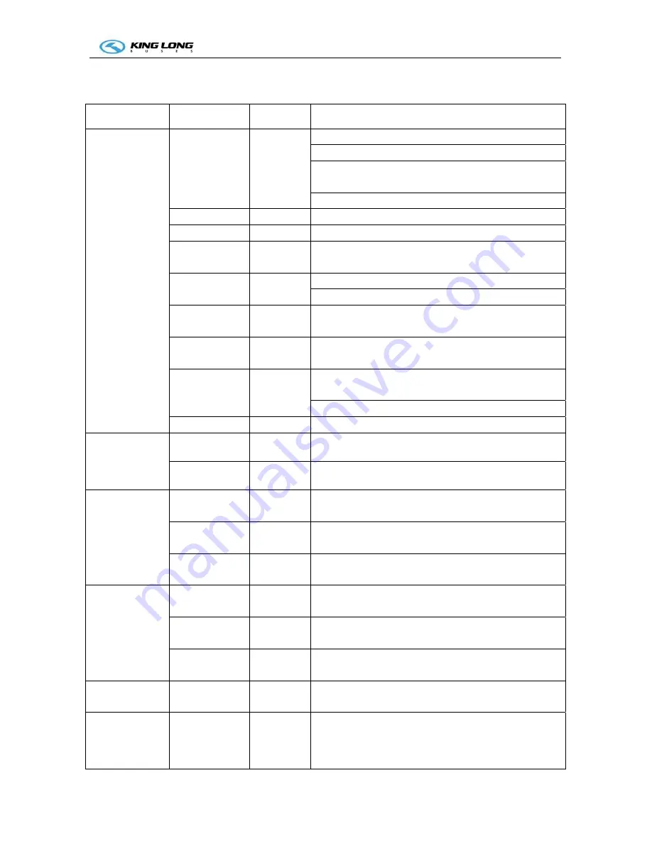
Maintenance operation and regulation every 10000km or 3 months depend on whichever occurs first.
Every 10000km include every 5000km maintenance operation
System Item Operation
Technical
requirement
Engine
Oil Replace
Check oil surface within required range
Check engine and oil seal without apparent leakage
Replace oil when engine water temperature is over 60
℃
,
for removing the impurity
Oil level more than CF
Oil filter
Replace
Before installation add 1/2—3/4 to filter
Air filter
Check
Clean air filter element
Air inlet/ outlet
system
Check
No air leakage, no damage, each clip fastening good
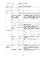
Cooling system
and Intercooler
Check
No leakage, each clip without damage or loosen
Water tank without leakage, damage, fouling
Coolant filter
Replace
Before re-install the coolant filter, daubs the 15W-40
lubricate oil on the interface of the sealing ring.
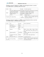
Fuel pump
installation
Check
No leakage
Air compressor
Check
No air, oil, coolant leakage,
lock nut and bolt no loosen
or damage
No carbon deposit
Brake system
Check
No leakage
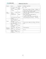
Propeller shaft
fastening bolt
Check and
fasten
Propeller shaft flange fastening bolts not loosening
universal joint
Check and
fasten
Universal joint each bearing no loosening or damage
Front axle
(
DF
or FS series
)
Brake bottom
board
Not
applicable
No loosening
Hub bear
Not
applicable
No loosening
Brake plate
Not
applicable
Change the brake plate when plate abrasion more than
limit pit.
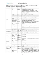
Rear axle
(
DF or FS
series
)
Brake bottom
board
Not
applicable
No loosening
Hub bear
Not
applicable
No loosening
Brake plate
Not
applicable
Change the brake plate when plate abrasion more than
limit pit.
The leaf
Suspension
Leaf spring
Not
applicable
Each fastening bolt not loosening, leaf spring no broken
piece, no apparent change of elasticity
Brake system
Rear braking
system
Check
Check brake frication piece thickness within required
range by check port, visual check brake adjust arm
working condition, running and stop brake good, each
brake pipeline and air line no leakage
Summary of Contents for XMQ6127 series
Page 18: ...Operation Instruction CI 1 Figure 17 Set MotPPR Figure 18 Clear Trip A Figure 19 Clear Trip B...
Page 32: ...Operation Instruction P A 1 2 Control panel operation...
Page 33: ...Operation Instruction P A 1...
Page 34: ...Operation Instruction P A 1...
Page 35: ...Operation Instruction P A 1...
Page 36: ...Operation Instruction P A 1...
Page 41: ...Operation Instruction 0 G 1 1 1 2 2 Pushbutton Settings...
Page 42: ...Operation Instruction 0 G 1 1 2 Starting the Engine 1 3 Selecting the Gear...
Page 43: ...Operation Instruction 0 G 1 1 4 Setting Off 1 5 Driving Ranges...
Page 44: ...Operation Instruction 0 G 1 1 5 1 Downhill Travel 1 5 2 Downhill Travel 1 5 3 Kickdown...
Page 46: ...Operation Instruction 0 G 1 1 6 Stopping Parking...
Page 51: ...Operation Instruction 0 G 1 1 11 1 Limp Home Mode 1 12 Auxiliary Control Unit...
Page 52: ...Operation Instruction 0 G 1 1 12 1 Operating Instructions for the Auxiliary Control Unit...
Page 53: ...Operation Instruction 0 AB 1 WABCO ABS BASIC INTRODUCTION...
Page 54: ...Operation Instruction 0 AB 1...
Page 55: ...Operation Instruction 0 AB 1...
Page 56: ...Operation Instruction 0 AB 1...
Page 57: ...Operation Instruction 0 AB 1...
Page 58: ...Operation Instruction 0 EC 1 ECAS System Introduction 1 System introduction...
Page 59: ...Operation Instruction 0 EC 1 3 System function...
Page 60: ...Operation Instruction 0 EC 1...
Page 77: ...Operation Instruction 0 E 1 CAN bus module...
Page 158: ...Appendix A 4 Air braking schematic diagram...
Page 159: ...A 5 Electric schematic diagram of the complete vehicle 1...
Page 160: ...A 6 Electric schematic diagram of the complete vehicle 2...
Page 161: ...A 7 Electric schematic diagram of the complete vehicle 3...
Page 162: ...A 8 Electric schematic diagram of the complete vehicle 4...


