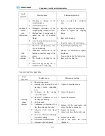
Common trouble and elimination
C-13
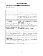
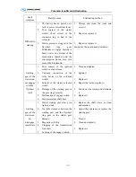
Fault
symptom
Possible cause
Eliminating method
Misproportion
or untimely
tire wear
3.
Others
1)
Breakdown caused by the
abrupt starting or the emergent
braking
2)
Overloading
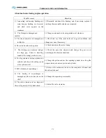
1) Correct the driving pattern
2) Make the loading according to the
specified capacity
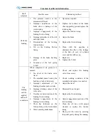
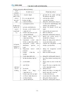
Heavy
operation of
the steering
wheel (the
steering
system
breakdown)
1.
Too low oil level
2.
Lubricant deterioration or
impurity in it
3.
Abrasion of the steering
junction
4.
Fault of the power steering
system
5.
Excessive lubricant resistance
caused by the pipeline sunken
6.
Too low oil pressure caused
by the ineffective hydraulic
pump
7.
There has air in the hydraulic
pipeline
8.
Malfunction of rotary valve
9.
Abrasion or damage of the
power cylinder and damage of
the piston O -ring
10.
Too much leakage of the oil
inside the steering gear
housing
1.
Add the lubricant to the given
level
2.
Replace the lubricant
3.
Replace the ball stud
4.
Overhaul and eliminate trouble.
5.
Measure the backpressure and
repair or replace the pipeline in
case of the set value exceeded
6.
Measure the oil pressure and the
flow volume; disassemble and
repair the hydraulic pump if the
set value belowed
7.
Bleed air and add oil.
8.
Disassemble and repair rotary
valve.
9.
Disassemble and repair.
10.
Disassmeble and repair steering
housing.
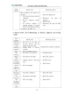
Heavy
operation of
the steering
wheel
(breakdown
of the front
axle)
1.
Improper adjustment of the
wheel alignment (excessive
caster angle)
2.
Too little clearance between
the king pin and bushing
3.
Inverse installation of the
thrust bearing
4.
Inadequate lubrication of the
front axle parts
5.
Over tight or loose connection
of the bull
6.
Too low tire pressure
7.
Excessive abrasion of the tire
1.
Check and adjust the wheel
alignment
2.
Check and adjust the clearance
3.
Adjust the installation
4.
Add the grease to the front axle
5.
Check and lubricate the bulb stud
6.
Inflate to the rated pressure
7.
Replace the tire
Summary of Contents for XMQ6127 series
Page 18: ...Operation Instruction CI 1 Figure 17 Set MotPPR Figure 18 Clear Trip A Figure 19 Clear Trip B...
Page 32: ...Operation Instruction P A 1 2 Control panel operation...
Page 33: ...Operation Instruction P A 1...
Page 34: ...Operation Instruction P A 1...
Page 35: ...Operation Instruction P A 1...
Page 36: ...Operation Instruction P A 1...
Page 41: ...Operation Instruction 0 G 1 1 1 2 2 Pushbutton Settings...
Page 42: ...Operation Instruction 0 G 1 1 2 Starting the Engine 1 3 Selecting the Gear...
Page 43: ...Operation Instruction 0 G 1 1 4 Setting Off 1 5 Driving Ranges...
Page 44: ...Operation Instruction 0 G 1 1 5 1 Downhill Travel 1 5 2 Downhill Travel 1 5 3 Kickdown...
Page 46: ...Operation Instruction 0 G 1 1 6 Stopping Parking...
Page 51: ...Operation Instruction 0 G 1 1 11 1 Limp Home Mode 1 12 Auxiliary Control Unit...
Page 52: ...Operation Instruction 0 G 1 1 12 1 Operating Instructions for the Auxiliary Control Unit...
Page 53: ...Operation Instruction 0 AB 1 WABCO ABS BASIC INTRODUCTION...
Page 54: ...Operation Instruction 0 AB 1...
Page 55: ...Operation Instruction 0 AB 1...
Page 56: ...Operation Instruction 0 AB 1...
Page 57: ...Operation Instruction 0 AB 1...
Page 58: ...Operation Instruction 0 EC 1 ECAS System Introduction 1 System introduction...
Page 59: ...Operation Instruction 0 EC 1 3 System function...
Page 60: ...Operation Instruction 0 EC 1...
Page 77: ...Operation Instruction 0 E 1 CAN bus module...
Page 158: ...Appendix A 4 Air braking schematic diagram...
Page 159: ...A 5 Electric schematic diagram of the complete vehicle 1...
Page 160: ...A 6 Electric schematic diagram of the complete vehicle 2...
Page 161: ...A 7 Electric schematic diagram of the complete vehicle 3...
Page 162: ...A 8 Electric schematic diagram of the complete vehicle 4...


