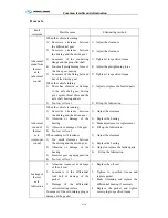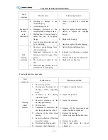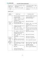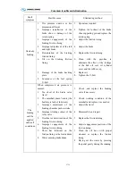
Common trouble and elimination
C-17
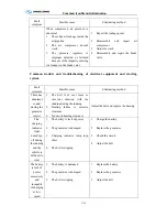
Fault
symptom
Possible cause
Eliminating method
Difficult in
starting
1.
The battery has no power, or is
lack of power or terminal loose
2.
Poor contact of the starter
switch, short circuit of the
connector lug or bad of the
solenoid
3.
Starter pinion is clogged in the
flywheel ring gear.
Furthermore, engine bearing is
burnt ,water on external of the
combustion chamber and the
consumption frozen may also
caused the breakdown
1.
Charge and clean the joint and
screw it
2.
Repair or replace it
3.
Repair or replace it
Found out the reason and eliminate it
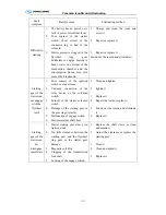
Starting
gear of the
starter can
not engage
with the
flywheel
teeth
1.
Poor contact of the ignition
switch or socket loose
2.
Unsteady connection of the
relay device or the solenoid
switch
3.
Turnoff of the starter solenoid
switch
4.
Damage of the starting gear or
the gear ring of starter
5.
Malfunction of engage switch
6.
Starter armature shaft bent
1.
Clean and tighten
2.
tighten it
3.
Replace it
4.
Repair the teeth or replace it
5.
Found out the reason and eliminate
it
6.
Replace it
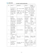
Starting
gear of the
starter can
not
disengage
completely
1.
Starter starting gear sleeve too
tight or stuck
2.
Too little clearance between the
starting gear and the flywheel
ring gear or the starter gear
damage
3.
Magnetic coil dirty
4.
Clogging of the transmission
fork shaft
5.
Locking of the engage switch
1.
Replace the shaft sleeve or clean
and amend it
2.
Adjust the clearance or replace the
starting gear
3.
Clean it
4.
Clean and adjust it
5.
Replace it
Summary of Contents for XMQ6127 series
Page 18: ...Operation Instruction CI 1 Figure 17 Set MotPPR Figure 18 Clear Trip A Figure 19 Clear Trip B...
Page 32: ...Operation Instruction P A 1 2 Control panel operation...
Page 33: ...Operation Instruction P A 1...
Page 34: ...Operation Instruction P A 1...
Page 35: ...Operation Instruction P A 1...
Page 36: ...Operation Instruction P A 1...
Page 41: ...Operation Instruction 0 G 1 1 1 2 2 Pushbutton Settings...
Page 42: ...Operation Instruction 0 G 1 1 2 Starting the Engine 1 3 Selecting the Gear...
Page 43: ...Operation Instruction 0 G 1 1 4 Setting Off 1 5 Driving Ranges...
Page 44: ...Operation Instruction 0 G 1 1 5 1 Downhill Travel 1 5 2 Downhill Travel 1 5 3 Kickdown...
Page 46: ...Operation Instruction 0 G 1 1 6 Stopping Parking...
Page 51: ...Operation Instruction 0 G 1 1 11 1 Limp Home Mode 1 12 Auxiliary Control Unit...
Page 52: ...Operation Instruction 0 G 1 1 12 1 Operating Instructions for the Auxiliary Control Unit...
Page 53: ...Operation Instruction 0 AB 1 WABCO ABS BASIC INTRODUCTION...
Page 54: ...Operation Instruction 0 AB 1...
Page 55: ...Operation Instruction 0 AB 1...
Page 56: ...Operation Instruction 0 AB 1...
Page 57: ...Operation Instruction 0 AB 1...
Page 58: ...Operation Instruction 0 EC 1 ECAS System Introduction 1 System introduction...
Page 59: ...Operation Instruction 0 EC 1 3 System function...
Page 60: ...Operation Instruction 0 EC 1...
Page 77: ...Operation Instruction 0 E 1 CAN bus module...
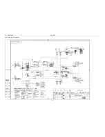
Page 158: ...Appendix A 4 Air braking schematic diagram...
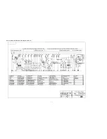
Page 159: ...A 5 Electric schematic diagram of the complete vehicle 1...
Page 160: ...A 6 Electric schematic diagram of the complete vehicle 2...
Page 161: ...A 7 Electric schematic diagram of the complete vehicle 3...
Page 162: ...A 8 Electric schematic diagram of the complete vehicle 4...

