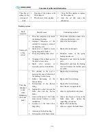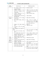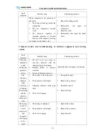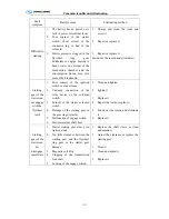
Common trouble and elimination
C-19
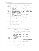
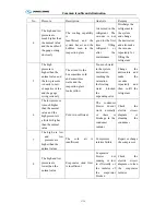
No. Pressure
Description
Analysis
Remedy
4
The high and low
pressure are
much higher than
the normal value
and the needle of
the gauge swing
obviously
The cooling capability
is
Insufficient and the
system has air and the
bubbles seen in the
inspection glass
Air mixed in the
refrigerant The
vacuum is not
good for the first
time filling
refrigerant or
after the
maintenance
Discharge the
refrigerant in
the system
and change
the desiccators
and also make
the vacuum
repeatedly for
filling the
refrigerant
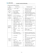
5
The high
pressure is
higher than the
normal value and
the low pressure
is nearly to zero
or negative value
and the gauge
swing seriously
The air sent to the
bus sometime cold
and sometimes
warm and the
inspection glass
looks yellow
Too much water
in the system
desiccators
reaching the
saturation
the frosting
water blocked
the
expanding valve
Change the
desiccators and
make the
vacuum
repeatedly and
then re-fill the
refrigerant
6
The low pressure
is much higher
than the normal
value and the
high pressure is
a little bit higher
than the normal
value
Cold is in sufficient
The condenser
blower doesn’t
work normally
or there is
blockage in the
condenser
radiator
Check the
electric circuit
diagram or
cleaning the
condenser
7
The high are low
and low
pressure are
higher than the
normal values
The cold air is
insufficient
Compressor
interior failure
Repair or change
the compressor
8
The high and low
pressure are
lower than the
normal value
Evaporator wind flow
is insufficient
Evaporator
blower not
running or low
in efficiently or
the radiator of
the evaporator
blocked
Check the
electric circuit
diagram or clean
the evaporator
radiator
Summary of Contents for XMQ6127 series
Page 18: ...Operation Instruction CI 1 Figure 17 Set MotPPR Figure 18 Clear Trip A Figure 19 Clear Trip B...
Page 32: ...Operation Instruction P A 1 2 Control panel operation...
Page 33: ...Operation Instruction P A 1...
Page 34: ...Operation Instruction P A 1...
Page 35: ...Operation Instruction P A 1...
Page 36: ...Operation Instruction P A 1...
Page 41: ...Operation Instruction 0 G 1 1 1 2 2 Pushbutton Settings...
Page 42: ...Operation Instruction 0 G 1 1 2 Starting the Engine 1 3 Selecting the Gear...
Page 43: ...Operation Instruction 0 G 1 1 4 Setting Off 1 5 Driving Ranges...
Page 44: ...Operation Instruction 0 G 1 1 5 1 Downhill Travel 1 5 2 Downhill Travel 1 5 3 Kickdown...
Page 46: ...Operation Instruction 0 G 1 1 6 Stopping Parking...
Page 51: ...Operation Instruction 0 G 1 1 11 1 Limp Home Mode 1 12 Auxiliary Control Unit...
Page 52: ...Operation Instruction 0 G 1 1 12 1 Operating Instructions for the Auxiliary Control Unit...
Page 53: ...Operation Instruction 0 AB 1 WABCO ABS BASIC INTRODUCTION...
Page 54: ...Operation Instruction 0 AB 1...
Page 55: ...Operation Instruction 0 AB 1...
Page 56: ...Operation Instruction 0 AB 1...
Page 57: ...Operation Instruction 0 AB 1...
Page 58: ...Operation Instruction 0 EC 1 ECAS System Introduction 1 System introduction...
Page 59: ...Operation Instruction 0 EC 1 3 System function...
Page 60: ...Operation Instruction 0 EC 1...
Page 77: ...Operation Instruction 0 E 1 CAN bus module...
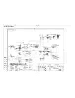
Page 158: ...Appendix A 4 Air braking schematic diagram...
Page 159: ...A 5 Electric schematic diagram of the complete vehicle 1...
Page 160: ...A 6 Electric schematic diagram of the complete vehicle 2...
Page 161: ...A 7 Electric schematic diagram of the complete vehicle 3...
Page 162: ...A 8 Electric schematic diagram of the complete vehicle 4...

