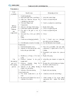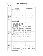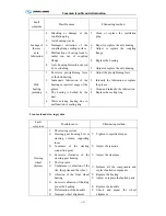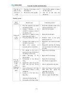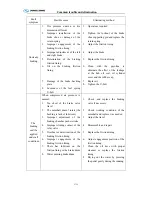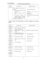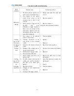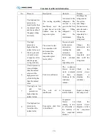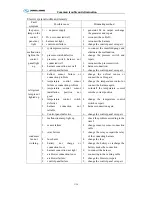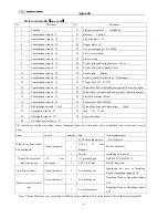
Common trouble and elimination
C-20
Electric system trouble and remedy
Fault
symptom
Possible cause
Eliminating method
the power
lamp on the
control
panel not
light
1.
+ no power supply
;
2.
D+ not connected well
;
3.
harness not tight
;
4.
control unit failure
;
1.
generator D+ no output, exchange
the generator and repair
2.
reconnect the cable D+
;
3.
reconnect the harness
;
4.
change the control panel or repair
;
malfunction
light on the
control
panel light
up
1.
system pressure error
;
2.
pressure switch defective
;
3.
pressure switch harness not
connected well
;
4.
harness connection not well
;
5.
control panel failure
;
1.
to connect the manifold gauge and
eliminate the malfunction
;
2.
change the pressure switch and
repair
;
3.
reconnect the pressure switch
;
4.
harness connection;
5.
change the control panel or repair
;
refrigerant
lamp is not
lighted up
1.
defrost sensor failure or
connection problem
;
2.
temperature control sensor
failure or connection problem
;
3.
temperature control sensor
installation position not
good
;
4.
temperature control switch
defective
;
5.
harness connection not
reliable
;
6.
Control panel defective
1.
change the defrost sensor or
connect the cable again
;
2.
change the temperature control or
connect the harness again
;
3.
re-install the temperature control
into the correct position
;
4.
change the temperature control
switch or repair
;
5.
harness connection again
;
6.
change the control panel or repair
;
condenser
fan not
working
1.
malfunction lamp light up
;
2.
sensor failure
;
3.
relay failure
;
4.
fuse burnt
;
5.
battery not charge or
connection loose
;
6.
harness connection not tight
;
7.
air blower connection loose
;
8.
air blower failure;
9.
control panel failure
;
1.
check the problem according to the
item 2
;
2.
change sensor or sensor connection
cable
;
3.
change the relay or repair the relay
of the connecting harness
;
4.
change the fuse
;
5.
change the battery or recharge the
battery ,make the connection
;
6.
re-connect the harness
;
7.
connecting to the venting cable
;
8.
change the blower or repair
;
9.
change the control panel or repair
;
Summary of Contents for XMQ6127 series
Page 18: ...Operation Instruction CI 1 Figure 17 Set MotPPR Figure 18 Clear Trip A Figure 19 Clear Trip B...
Page 32: ...Operation Instruction P A 1 2 Control panel operation...
Page 33: ...Operation Instruction P A 1...
Page 34: ...Operation Instruction P A 1...
Page 35: ...Operation Instruction P A 1...
Page 36: ...Operation Instruction P A 1...
Page 41: ...Operation Instruction 0 G 1 1 1 2 2 Pushbutton Settings...
Page 42: ...Operation Instruction 0 G 1 1 2 Starting the Engine 1 3 Selecting the Gear...
Page 43: ...Operation Instruction 0 G 1 1 4 Setting Off 1 5 Driving Ranges...
Page 44: ...Operation Instruction 0 G 1 1 5 1 Downhill Travel 1 5 2 Downhill Travel 1 5 3 Kickdown...
Page 46: ...Operation Instruction 0 G 1 1 6 Stopping Parking...
Page 51: ...Operation Instruction 0 G 1 1 11 1 Limp Home Mode 1 12 Auxiliary Control Unit...
Page 52: ...Operation Instruction 0 G 1 1 12 1 Operating Instructions for the Auxiliary Control Unit...
Page 53: ...Operation Instruction 0 AB 1 WABCO ABS BASIC INTRODUCTION...
Page 54: ...Operation Instruction 0 AB 1...
Page 55: ...Operation Instruction 0 AB 1...
Page 56: ...Operation Instruction 0 AB 1...
Page 57: ...Operation Instruction 0 AB 1...
Page 58: ...Operation Instruction 0 EC 1 ECAS System Introduction 1 System introduction...
Page 59: ...Operation Instruction 0 EC 1 3 System function...
Page 60: ...Operation Instruction 0 EC 1...
Page 77: ...Operation Instruction 0 E 1 CAN bus module...
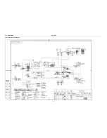
Page 158: ...Appendix A 4 Air braking schematic diagram...
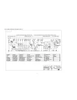
Page 159: ...A 5 Electric schematic diagram of the complete vehicle 1...
Page 160: ...A 6 Electric schematic diagram of the complete vehicle 2...
Page 161: ...A 7 Electric schematic diagram of the complete vehicle 3...
Page 162: ...A 8 Electric schematic diagram of the complete vehicle 4...


