Operation Instruction
P-H-1
Pre-heater Operation (Webasto)
1.
General
The standard digital timer enables you to preset the
start of the heater operation up to 7 days in
advance.
It is possible to program 3 different starting times,
only one of which can be activated.
The standard digital timer features a wakeup alarm
function.
When the ignition switched on, the timer displays
the current time and the day of the week.
When the heater is switched on, the display and
the buttons are illuminated.
After the power supply has been connected,
all symbols on the display will flash.
The current time and weekday must be set.
2.
Operation
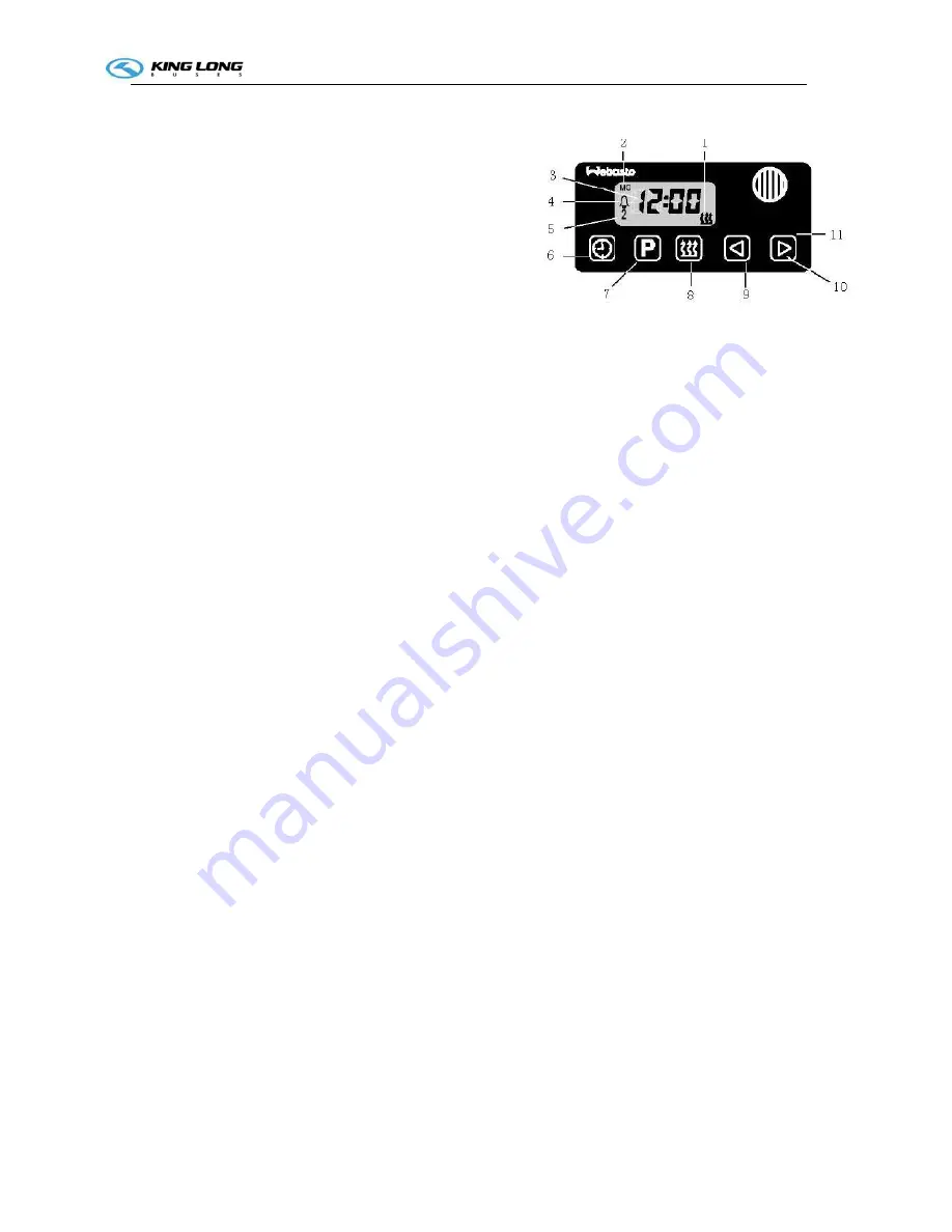
The timer can be operated in that all flashing symbols
can be adjusted by means of the 10 and 9 buttons.
If the buttons are not pressed within 5 seconds,
the time displayed will be stored.
If the 10 and 9 buttons are pressed for more than
2 seconds, the fast time-setting mode is activated.
If the ignition is switched off while the heater is operating in the continuous mode, the
remaining operating time of 15 minutes is displayed and the heater continues to operate for this
period of time.
3.
Switch the heater on
Manually: by pressing the button 8 (continuous heating mode)
Automatically: by programming the heater starting time
4.
Switch the heater off
Manually: by pressing the button 8
Automatically: after the programmed operating time has elapsed.
With the heater running: by programming the remaining operating time
5.
Setting time/day of the week
Press the 6 button for more than 2 seconds-time of the day if flashing-and set the clock using
the 9 and 10 buttons. Day of the week is flashing – adjust the day of the week.
6.
Viewing the time
With the ignition switched off: press the 6 button.
7.
Programming heater starting time:
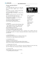
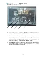
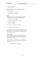
Standard Timer
heater “on” indicator
day of the week
time display
memory location
alarm indicator
time
program selection
instant heating
reverse
forward
panel
Summary of Contents for XMQ6127 series
Page 18: ...Operation Instruction CI 1 Figure 17 Set MotPPR Figure 18 Clear Trip A Figure 19 Clear Trip B...
Page 32: ...Operation Instruction P A 1 2 Control panel operation...
Page 33: ...Operation Instruction P A 1...
Page 34: ...Operation Instruction P A 1...
Page 35: ...Operation Instruction P A 1...
Page 36: ...Operation Instruction P A 1...
Page 41: ...Operation Instruction 0 G 1 1 1 2 2 Pushbutton Settings...
Page 42: ...Operation Instruction 0 G 1 1 2 Starting the Engine 1 3 Selecting the Gear...
Page 43: ...Operation Instruction 0 G 1 1 4 Setting Off 1 5 Driving Ranges...
Page 44: ...Operation Instruction 0 G 1 1 5 1 Downhill Travel 1 5 2 Downhill Travel 1 5 3 Kickdown...
Page 46: ...Operation Instruction 0 G 1 1 6 Stopping Parking...
Page 51: ...Operation Instruction 0 G 1 1 11 1 Limp Home Mode 1 12 Auxiliary Control Unit...
Page 52: ...Operation Instruction 0 G 1 1 12 1 Operating Instructions for the Auxiliary Control Unit...
Page 53: ...Operation Instruction 0 AB 1 WABCO ABS BASIC INTRODUCTION...
Page 54: ...Operation Instruction 0 AB 1...
Page 55: ...Operation Instruction 0 AB 1...
Page 56: ...Operation Instruction 0 AB 1...
Page 57: ...Operation Instruction 0 AB 1...
Page 58: ...Operation Instruction 0 EC 1 ECAS System Introduction 1 System introduction...
Page 59: ...Operation Instruction 0 EC 1 3 System function...
Page 60: ...Operation Instruction 0 EC 1...
Page 77: ...Operation Instruction 0 E 1 CAN bus module...
Page 158: ...Appendix A 4 Air braking schematic diagram...
Page 159: ...A 5 Electric schematic diagram of the complete vehicle 1...
Page 160: ...A 6 Electric schematic diagram of the complete vehicle 2...
Page 161: ...A 7 Electric schematic diagram of the complete vehicle 3...
Page 162: ...A 8 Electric schematic diagram of the complete vehicle 4...

