Operation Instruction
0-T-2
④
. Hand Wash System: The toilet is
equipped with a water pump for the hand wash
faucet. When the button is pushed, the water
pump is turned on for a certain period of time
(normally 3-5 seconds). The water will keep
running until the time is up. The waste water is
drained to a holding tank. One can push the
soap dispenser for the hand wash soap.
⑤
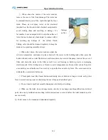
. Toilet Flush System: Push the
flush button, produce stream (about
300-500ml), the drain valve will open
in a short time and the waste in the
toilet will be flushed into the
waster-water holding tank.
⑥
. Door Seal and Ventilation System: The door of the toilet module has a seal strip, which
prevents any odor from getting into the bus; The toilet module is equipped with a fan (a dual fan with
inner and outer two different uses, the fan will be operated in a low speed to vent the air constantly,
when the toilet is vacant, however, it will be operated in high speed for ventilation, when the toilet is
occupied. The outer fan operates in a normal speed), keeping Fresh air in the bus with automatically
ventilation.
⑦
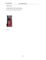
. Handles: For the safety and convenience of the
passengers, the toilet module has installed safety
handles inside or also outside of the toilet module.
⑧
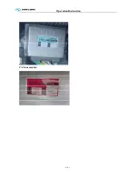
. The dashboard indication: in the signal area of dashboard, it can indicate in time: vacant or
occupied, the water state of fresh-water and waste-water holding tank, and emergency (Alarm button
is installed in toilet) and so on, which makes drivers know the usage status of the toilet.
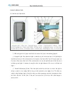
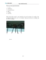
Faucet
Soap dispenser
Flush button
Toilet cover
Internal
handle
Hand-wash
button
Summary of Contents for XMQ6127 series
Page 18: ...Operation Instruction CI 1 Figure 17 Set MotPPR Figure 18 Clear Trip A Figure 19 Clear Trip B...
Page 32: ...Operation Instruction P A 1 2 Control panel operation...
Page 33: ...Operation Instruction P A 1...
Page 34: ...Operation Instruction P A 1...
Page 35: ...Operation Instruction P A 1...
Page 36: ...Operation Instruction P A 1...
Page 41: ...Operation Instruction 0 G 1 1 1 2 2 Pushbutton Settings...
Page 42: ...Operation Instruction 0 G 1 1 2 Starting the Engine 1 3 Selecting the Gear...
Page 43: ...Operation Instruction 0 G 1 1 4 Setting Off 1 5 Driving Ranges...
Page 44: ...Operation Instruction 0 G 1 1 5 1 Downhill Travel 1 5 2 Downhill Travel 1 5 3 Kickdown...
Page 46: ...Operation Instruction 0 G 1 1 6 Stopping Parking...
Page 51: ...Operation Instruction 0 G 1 1 11 1 Limp Home Mode 1 12 Auxiliary Control Unit...
Page 52: ...Operation Instruction 0 G 1 1 12 1 Operating Instructions for the Auxiliary Control Unit...
Page 53: ...Operation Instruction 0 AB 1 WABCO ABS BASIC INTRODUCTION...
Page 54: ...Operation Instruction 0 AB 1...
Page 55: ...Operation Instruction 0 AB 1...
Page 56: ...Operation Instruction 0 AB 1...
Page 57: ...Operation Instruction 0 AB 1...
Page 58: ...Operation Instruction 0 EC 1 ECAS System Introduction 1 System introduction...
Page 59: ...Operation Instruction 0 EC 1 3 System function...
Page 60: ...Operation Instruction 0 EC 1...
Page 77: ...Operation Instruction 0 E 1 CAN bus module...
Page 158: ...Appendix A 4 Air braking schematic diagram...
Page 159: ...A 5 Electric schematic diagram of the complete vehicle 1...
Page 160: ...A 6 Electric schematic diagram of the complete vehicle 2...
Page 161: ...A 7 Electric schematic diagram of the complete vehicle 3...
Page 162: ...A 8 Electric schematic diagram of the complete vehicle 4...

