Operation Instruction
0-T-3
⑨
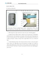
. Fresh -Water Holding Tank System: The holding tank is to store the fresh water for toilet flush and
hand wash, please check the water level before use. Make sure water is full. If the Water Level Warning
System indicates lack of water, please watering in time. Before watering, taking out overflow pipe,
watering overflow pipe until fresh water tank is full.
⑩
. Waste-Water Holding Tank System: The holding tank is to store the waste water after toilet flush
and hand wash. When the Warning System indicates that the holding tank is full, one should stop using
the toilet immediately. After the coach arrives at the tank evacuating area, turning the handle of the
evacuation valve will open the valve to drain the holding tank. Turning the handle back after evacuation
will close the evacuation valve.
(2). Caution in Use
①
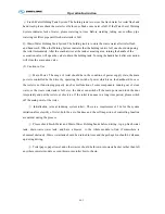
. Main Power: The usage of toilet should be in the condition of power supply state, the main
power is controlled be the driver by operating the switch of power which is on the dashboard. In case,
the toilet is not functioning properly (such as malfunction of some components, running out of clean
water, or the waste water tank is full, etc.), the driver can switch off the main power and lock the door
temporarily and put the toilet out of service. If the toilet is nonuse in a long time period, please switch
off the main power of the toilet.
②
. Initialization (aim at inducing system toilet): There is a requirement of 50s for the system
initiation after electrify of toilet, both the act of deduce and the self inspection of controlling function
are natural during the process.
③
. Please check Fresh-Water and Waste-Water Holding Tanks before driving, top up fresh water
tank, drain waste water tank, and have a browse to the whole module to find if somewhere is
abnormal obviously. Waste water tank should be drained in time and the garbage bin should be cleaned
up during driving.
④
. Toilet paper, paper towel and other wastes should be thrown into waste basket, rather than left
anywhere in toilet module or even thrown into toilet bowl or basin.
Summary of Contents for XMQ6127 series
Page 18: ...Operation Instruction CI 1 Figure 17 Set MotPPR Figure 18 Clear Trip A Figure 19 Clear Trip B...
Page 32: ...Operation Instruction P A 1 2 Control panel operation...
Page 33: ...Operation Instruction P A 1...
Page 34: ...Operation Instruction P A 1...
Page 35: ...Operation Instruction P A 1...
Page 36: ...Operation Instruction P A 1...
Page 41: ...Operation Instruction 0 G 1 1 1 2 2 Pushbutton Settings...
Page 42: ...Operation Instruction 0 G 1 1 2 Starting the Engine 1 3 Selecting the Gear...
Page 43: ...Operation Instruction 0 G 1 1 4 Setting Off 1 5 Driving Ranges...
Page 44: ...Operation Instruction 0 G 1 1 5 1 Downhill Travel 1 5 2 Downhill Travel 1 5 3 Kickdown...
Page 46: ...Operation Instruction 0 G 1 1 6 Stopping Parking...
Page 51: ...Operation Instruction 0 G 1 1 11 1 Limp Home Mode 1 12 Auxiliary Control Unit...
Page 52: ...Operation Instruction 0 G 1 1 12 1 Operating Instructions for the Auxiliary Control Unit...
Page 53: ...Operation Instruction 0 AB 1 WABCO ABS BASIC INTRODUCTION...
Page 54: ...Operation Instruction 0 AB 1...
Page 55: ...Operation Instruction 0 AB 1...
Page 56: ...Operation Instruction 0 AB 1...
Page 57: ...Operation Instruction 0 AB 1...
Page 58: ...Operation Instruction 0 EC 1 ECAS System Introduction 1 System introduction...
Page 59: ...Operation Instruction 0 EC 1 3 System function...
Page 60: ...Operation Instruction 0 EC 1...
Page 77: ...Operation Instruction 0 E 1 CAN bus module...
Page 158: ...Appendix A 4 Air braking schematic diagram...
Page 159: ...A 5 Electric schematic diagram of the complete vehicle 1...
Page 160: ...A 6 Electric schematic diagram of the complete vehicle 2...
Page 161: ...A 7 Electric schematic diagram of the complete vehicle 3...
Page 162: ...A 8 Electric schematic diagram of the complete vehicle 4...

