Operation Instruction
0-T-4
⑤
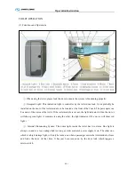
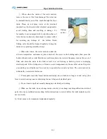
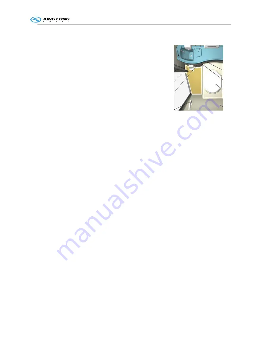
. When clean the inside of the toilet module,
remove the cover of the floor drainage. The water can
be drained directly out of the coach through the floor
drain. Please do not spray water at the electrical
junction box, the fan, and other electrical equipment to
avoid wetting them and resulting in damage. It’s
favourable to use a damped cloth to wipe the surface of
toilet, but not to have any hard object to contact with it
for avoiding any damage of the surface finish.
Sliding valve should be cleansed regularly to keep the
drain valve operating smoothly always.
⑥
.When shut down the toilet module under the
sub-zero temperature environment, please drain all the water in the holding tanks, then press the
button of hand wash or toilet flush for several times, drain the water in the pump, turn on the cover of
filter, and drain the water in the filter as well to avoid freezing to build up water or damaging
electrical parts. If the sliding valve is frozen or water components are frozen, toilet can not be put in
use until they are all unfrozen. You never try to open the frozen valve by force. The valve needs to be
defrosted by warm water before use.
⑦
. Please push/ touch the faucet button moderately, do not hold on to longer or turn on by great
force to avoid wasting water or shortening the use life-span of electrical parts.
⑧
. Do not insert or pull out casually during any electrical part working.
⑨
.When use the toilet, do not change inside circuitry or exchange any disqualification electrical
parts; In case any malfunction occurring, follow instructions to solve it before the toilet module is put in
use renewedly.
⑩
. Toilet needs to be cleaned and maintained regularly.
Drainage
on floor
Summary of Contents for XMQ6127 series
Page 18: ...Operation Instruction CI 1 Figure 17 Set MotPPR Figure 18 Clear Trip A Figure 19 Clear Trip B...
Page 32: ...Operation Instruction P A 1 2 Control panel operation...
Page 33: ...Operation Instruction P A 1...
Page 34: ...Operation Instruction P A 1...
Page 35: ...Operation Instruction P A 1...
Page 36: ...Operation Instruction P A 1...
Page 41: ...Operation Instruction 0 G 1 1 1 2 2 Pushbutton Settings...
Page 42: ...Operation Instruction 0 G 1 1 2 Starting the Engine 1 3 Selecting the Gear...
Page 43: ...Operation Instruction 0 G 1 1 4 Setting Off 1 5 Driving Ranges...
Page 44: ...Operation Instruction 0 G 1 1 5 1 Downhill Travel 1 5 2 Downhill Travel 1 5 3 Kickdown...
Page 46: ...Operation Instruction 0 G 1 1 6 Stopping Parking...
Page 51: ...Operation Instruction 0 G 1 1 11 1 Limp Home Mode 1 12 Auxiliary Control Unit...
Page 52: ...Operation Instruction 0 G 1 1 12 1 Operating Instructions for the Auxiliary Control Unit...
Page 53: ...Operation Instruction 0 AB 1 WABCO ABS BASIC INTRODUCTION...
Page 54: ...Operation Instruction 0 AB 1...
Page 55: ...Operation Instruction 0 AB 1...
Page 56: ...Operation Instruction 0 AB 1...
Page 57: ...Operation Instruction 0 AB 1...
Page 58: ...Operation Instruction 0 EC 1 ECAS System Introduction 1 System introduction...
Page 59: ...Operation Instruction 0 EC 1 3 System function...
Page 60: ...Operation Instruction 0 EC 1...
Page 77: ...Operation Instruction 0 E 1 CAN bus module...
Page 158: ...Appendix A 4 Air braking schematic diagram...
Page 159: ...A 5 Electric schematic diagram of the complete vehicle 1...
Page 160: ...A 6 Electric schematic diagram of the complete vehicle 2...
Page 161: ...A 7 Electric schematic diagram of the complete vehicle 3...
Page 162: ...A 8 Electric schematic diagram of the complete vehicle 4...

