Operation Instruction
0-K-2
Door emergency switch
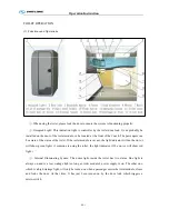
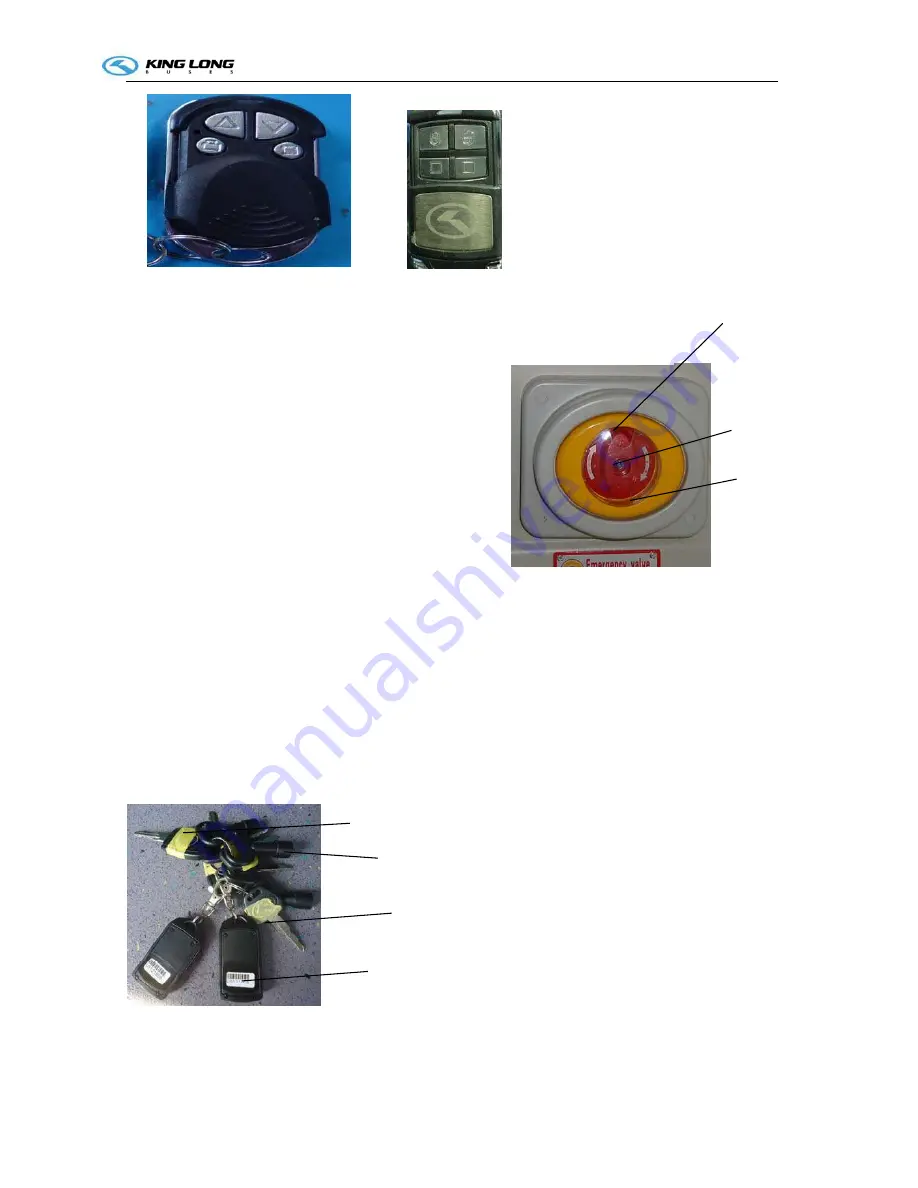
The model 1 door emergency switch is located on upside of the gate ingress.
Operation tips: 1) Please press the red button 1 and flick open the valve cover 2.
2) Please rotate the red handle switch 3 clockwise up to 90 degree.
3) The air valve begin to deflate , and next step may pull the door opened accordingly.
Special attention:
The door emergency switch is only used in the emergency state. Please don't rotate
the door emergency switch in driving for fear of danger.
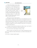
The vehicle uses the keys as follows:
Door remote controller 2
Door remote controller 1
Model 1
1
3
2
Door remote key
Door key
Cabin door key
Ignition key
Summary of Contents for XMQ6127 series
Page 18: ...Operation Instruction CI 1 Figure 17 Set MotPPR Figure 18 Clear Trip A Figure 19 Clear Trip B...
Page 32: ...Operation Instruction P A 1 2 Control panel operation...
Page 33: ...Operation Instruction P A 1...
Page 34: ...Operation Instruction P A 1...
Page 35: ...Operation Instruction P A 1...
Page 36: ...Operation Instruction P A 1...
Page 41: ...Operation Instruction 0 G 1 1 1 2 2 Pushbutton Settings...
Page 42: ...Operation Instruction 0 G 1 1 2 Starting the Engine 1 3 Selecting the Gear...
Page 43: ...Operation Instruction 0 G 1 1 4 Setting Off 1 5 Driving Ranges...
Page 44: ...Operation Instruction 0 G 1 1 5 1 Downhill Travel 1 5 2 Downhill Travel 1 5 3 Kickdown...
Page 46: ...Operation Instruction 0 G 1 1 6 Stopping Parking...
Page 51: ...Operation Instruction 0 G 1 1 11 1 Limp Home Mode 1 12 Auxiliary Control Unit...
Page 52: ...Operation Instruction 0 G 1 1 12 1 Operating Instructions for the Auxiliary Control Unit...
Page 53: ...Operation Instruction 0 AB 1 WABCO ABS BASIC INTRODUCTION...
Page 54: ...Operation Instruction 0 AB 1...
Page 55: ...Operation Instruction 0 AB 1...
Page 56: ...Operation Instruction 0 AB 1...
Page 57: ...Operation Instruction 0 AB 1...
Page 58: ...Operation Instruction 0 EC 1 ECAS System Introduction 1 System introduction...
Page 59: ...Operation Instruction 0 EC 1 3 System function...
Page 60: ...Operation Instruction 0 EC 1...
Page 77: ...Operation Instruction 0 E 1 CAN bus module...
Page 158: ...Appendix A 4 Air braking schematic diagram...
Page 159: ...A 5 Electric schematic diagram of the complete vehicle 1...
Page 160: ...A 6 Electric schematic diagram of the complete vehicle 2...
Page 161: ...A 7 Electric schematic diagram of the complete vehicle 3...
Page 162: ...A 8 Electric schematic diagram of the complete vehicle 4...


