Technical parameter and complete vehicle description
- 7 -
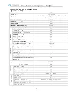
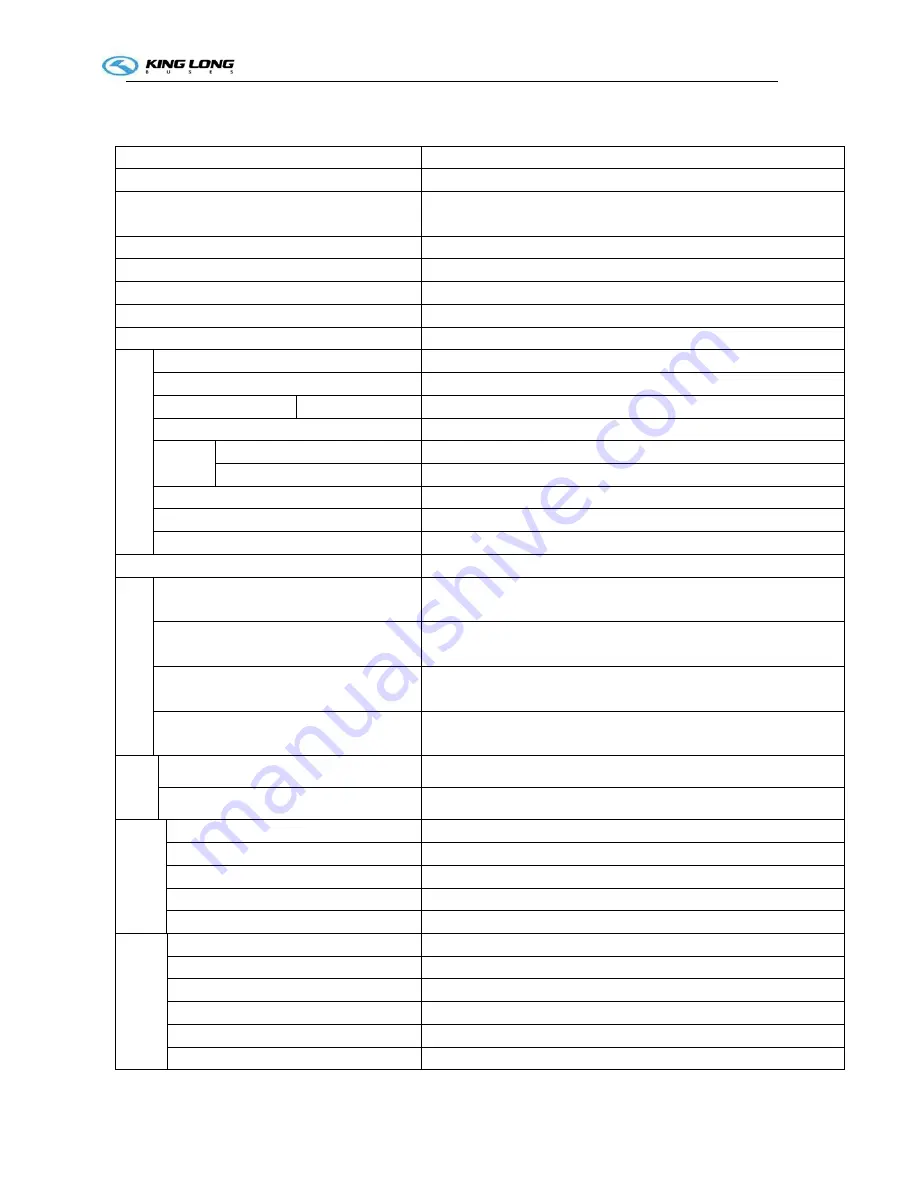
Technical parameters of the complete vehicle
(
vehicle No. GA200001
)
Product model
6127
Engine model
ISL8.9E5 400
Engine type
In-line six-cylinder water-cooling electrically controlled common rail
direct-injection diesel engine
Cylinder diameter ×stroke
(mm)
114×145
Displacement
(ml)
8900
Compression ratio
16.6:1
Rated capacity / rotation speed
(kw/rpm)
294/2100
Max. torque / rotation speed
(N
·
m/rpm)
1700/1300
D
im
e
n
s
io
n
s
Overall length
(mm)
12000
Overall width
(mm)
2490
Overall height
(mm)
Air spring
3800
Wheelbase
(mm)
6350
Wheel
track
front (mm)
2020
rear (mm)
1860
Minimum lift-off clearance
(mm)
240
Approach angle/ departure angle
(°)
10/9
Front overhang / rear overhang
(mm)
2380/3270
Rated
passenger
(driver included) (person)
49+1+1
Ma
ss
pa
ra
mete
r
Technically permissible maximum laden mass
(kg)
19000
Technically permissible maximum mass of
combination
(kg)
--
Technically permissible maximum laden mass for
front axle
(kg)
7500
Technically permissible maximum laden mass for
rear axle
(kg)
13000
W
h
e
e
l
Tire size
295/80R22.5
Tire inflation(MPa)
900
Performance
parameter
Max. speed
(km/h)
100
Fuel consumption
(L)
--
Maximum gradeability
(%)
≥20
Min. turning diameter
(m)
≤24
Parking slope (20%)
Parking for 5 minutes
Capacity data
Fuel tank(L)
300
Engine oil(L)
27.6
Transmission lubricant(L)
20(service oil change),30(dry oil fill)
Main reducing gear lubricant(L)
16
Power steering hydraulic oil(L)
8
clutch lubricant(L)
0
Summary of Contents for XMQ6127 series
Page 18: ...Operation Instruction CI 1 Figure 17 Set MotPPR Figure 18 Clear Trip A Figure 19 Clear Trip B...
Page 32: ...Operation Instruction P A 1 2 Control panel operation...
Page 33: ...Operation Instruction P A 1...
Page 34: ...Operation Instruction P A 1...
Page 35: ...Operation Instruction P A 1...
Page 36: ...Operation Instruction P A 1...
Page 41: ...Operation Instruction 0 G 1 1 1 2 2 Pushbutton Settings...
Page 42: ...Operation Instruction 0 G 1 1 2 Starting the Engine 1 3 Selecting the Gear...
Page 43: ...Operation Instruction 0 G 1 1 4 Setting Off 1 5 Driving Ranges...
Page 44: ...Operation Instruction 0 G 1 1 5 1 Downhill Travel 1 5 2 Downhill Travel 1 5 3 Kickdown...
Page 46: ...Operation Instruction 0 G 1 1 6 Stopping Parking...
Page 51: ...Operation Instruction 0 G 1 1 11 1 Limp Home Mode 1 12 Auxiliary Control Unit...
Page 52: ...Operation Instruction 0 G 1 1 12 1 Operating Instructions for the Auxiliary Control Unit...
Page 53: ...Operation Instruction 0 AB 1 WABCO ABS BASIC INTRODUCTION...
Page 54: ...Operation Instruction 0 AB 1...
Page 55: ...Operation Instruction 0 AB 1...
Page 56: ...Operation Instruction 0 AB 1...
Page 57: ...Operation Instruction 0 AB 1...
Page 58: ...Operation Instruction 0 EC 1 ECAS System Introduction 1 System introduction...
Page 59: ...Operation Instruction 0 EC 1 3 System function...
Page 60: ...Operation Instruction 0 EC 1...
Page 77: ...Operation Instruction 0 E 1 CAN bus module...
Page 158: ...Appendix A 4 Air braking schematic diagram...
Page 159: ...A 5 Electric schematic diagram of the complete vehicle 1...
Page 160: ...A 6 Electric schematic diagram of the complete vehicle 2...
Page 161: ...A 7 Electric schematic diagram of the complete vehicle 3...
Page 162: ...A 8 Electric schematic diagram of the complete vehicle 4...

