Vehicle Starting and Driving
S-11
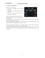
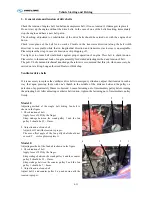
3. Tachometer working order
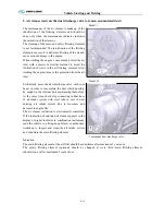
Indications on tachometer scale:
a.
Green zone – operating range of maximum
performance
b.
Yellow zone – a little high speed range (warning of
engine fault)
c.
Red zone – engine overspeed range (risk of
immediate engine damage)
Always observe tachometer while driving the vehicle.
Whenever possible keep engine running within the
economical range.
On downgrade, select an adequate gearbox speed ratio and monitor vehicle speed to avoid engine
operating in the danger range (red zone).
When the exhaust-brake is being operated on down grades, select an adequate gearbox speed ratio to keep
engine speed within efficient exhaust-brake operation
(
yellow
)
.
Always avoid engine over revving (red zone), as engine operation in this speed range can end up the
engine damage immediately or will seriously jeopardize its durability.
The yellow range with red reticle can be used occasionally when the exhaust-brake needs to be used at its
efficiency limit, however, at risk of engine durability. Therefore, do not operate in this range in a normal
or usual way.
Summary of Contents for XMQ6127 series
Page 18: ...Operation Instruction CI 1 Figure 17 Set MotPPR Figure 18 Clear Trip A Figure 19 Clear Trip B...
Page 32: ...Operation Instruction P A 1 2 Control panel operation...
Page 33: ...Operation Instruction P A 1...
Page 34: ...Operation Instruction P A 1...
Page 35: ...Operation Instruction P A 1...
Page 36: ...Operation Instruction P A 1...
Page 41: ...Operation Instruction 0 G 1 1 1 2 2 Pushbutton Settings...
Page 42: ...Operation Instruction 0 G 1 1 2 Starting the Engine 1 3 Selecting the Gear...
Page 43: ...Operation Instruction 0 G 1 1 4 Setting Off 1 5 Driving Ranges...
Page 44: ...Operation Instruction 0 G 1 1 5 1 Downhill Travel 1 5 2 Downhill Travel 1 5 3 Kickdown...
Page 46: ...Operation Instruction 0 G 1 1 6 Stopping Parking...
Page 51: ...Operation Instruction 0 G 1 1 11 1 Limp Home Mode 1 12 Auxiliary Control Unit...
Page 52: ...Operation Instruction 0 G 1 1 12 1 Operating Instructions for the Auxiliary Control Unit...
Page 53: ...Operation Instruction 0 AB 1 WABCO ABS BASIC INTRODUCTION...
Page 54: ...Operation Instruction 0 AB 1...
Page 55: ...Operation Instruction 0 AB 1...
Page 56: ...Operation Instruction 0 AB 1...
Page 57: ...Operation Instruction 0 AB 1...
Page 58: ...Operation Instruction 0 EC 1 ECAS System Introduction 1 System introduction...
Page 59: ...Operation Instruction 0 EC 1 3 System function...
Page 60: ...Operation Instruction 0 EC 1...
Page 77: ...Operation Instruction 0 E 1 CAN bus module...
Page 158: ...Appendix A 4 Air braking schematic diagram...
Page 159: ...A 5 Electric schematic diagram of the complete vehicle 1...
Page 160: ...A 6 Electric schematic diagram of the complete vehicle 2...
Page 161: ...A 7 Electric schematic diagram of the complete vehicle 3...
Page 162: ...A 8 Electric schematic diagram of the complete vehicle 4...

