Technical parameter and complete vehicle description
P-A-3
Low air flow rate: the temperature of air-return inside the bus is lower than 24
℃
(including 24 ).
℃
When switching air flow rate by different temperature, the switching confirm time is 30
seconds.
7)
Temperature control method
Using ON/OFF mode
:
the temperature controlling precision
(
DIF
)
is 2
℃
,
(FIX
SETTING)
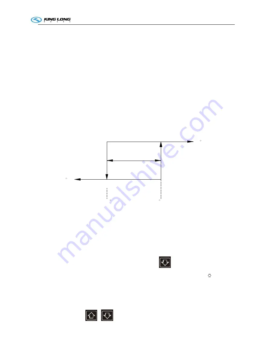
For example: the temperature controlling precision
(
DIF
)
is 2
℃
,
The setting temperature
is 25 .
℃
When the bus inside temperature is 30 :
℃
The cooling system will be stop (OFF) when the temperature reaching 25 .
℃
The cooling system will be start (ON) for cooling (COOLING) when the temperature is
over 27 . The cooling
℃
delay time is 10 seconds when it’s at the first starting, after this the
interval time is 30 seconds.
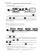
Tem perature
cycle2° C
(- C)
S etting tem perature
25°
C
25 C
O F F cooling m ode
27 C
(+ C)
on cooling m ode
8)
Strong cooling
This function of maintenance is used in the season which the air conditioner does not use
(
over
2 ins
℃
ide of bus
)
. The goal is provide the lubricant to the shaft sealing ring by the pressure of
the working compressor. Normally it works 10 minutes and once or twice every month.
9)
Operation of strong cooling
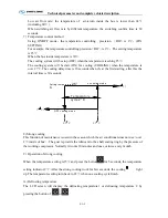
When the temperature setting is15 and press the bu
℃
tton
for 5 seconds, the temperature
setting indicator 2 . After the strong cooling work for few seconds, the cooling
℃
light
up. The temperature setting turn back to 22 when one cooling cycle finish.
℃
10)
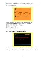
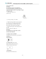
Defrosting temperature
The LCD screen will display the defrosting temperature1 or defrosting temperature 2 by
pressing the button of
or
.
Summary of Contents for XMQ6129Y series
Page 47: ...Technical parameter and complete vehicle description 0 T 1 TPMS OPERATION...
Page 48: ...Technical parameter and complete vehicle description 0 T 1...
Page 49: ...Technical parameter and complete vehicle description 0 T 1...
Page 50: ...Technical parameter and complete vehicle description 0 T 1...
Page 51: ...Technical parameter and complete vehicle description 0 T 1...
Page 52: ...Technical parameter and complete vehicle description 0 T 1...
Page 53: ...Technical parameter and complete vehicle description 0 T 1...
Page 54: ...Technical parameter and complete vehicle description 0 T 1...
Page 55: ...Technical parameter and complete vehicle description 0 T 1...
Page 56: ...Technical parameter and complete vehicle description 0 T 1...
Page 57: ...Technical parameter and complete vehicle description 0 T 1...
Page 63: ...Technical parameter and complete vehicle description 0 K 1 Lock1 Lock 2 Lock 3...
Page 157: ...Appendix A 4 Air braking schematic diagram...
Page 158: ...Appendix A 4 Electric schematic diagram of the complete vehicle 1...
Page 159: ...Appendix A 5 Electric schematic diagram of the complete vehicle 2...
Page 160: ...Appendix A 5 Electric schematic diagram of the complete vehicle 3...
Page 161: ...Appendix A 5 Electric schematic diagram of the complete vehicle 4...

