Appendix
7-2
Tightening torque of main bolts and nuts
Position
Tightening torque
(
N·m
)
Propeller shaft bolt
(
Bolt grade: 10.9 G
)
M16×1.5×L
270
~
330
lock nut, steering knuckle limiting bolt(M16)
80
~
100
Fixing nut, upper knuckle(M20)
280
~
350
Binding nut, tie rod
(
M12
)
75
~
100
fixing nut ,ball pin of steering drag rod
(
M24
)
280
~
300
Lock nut, steering wheel (M18)
60
~
80
fixing bolt , pitman arm and steering gear(M22)
570
Front tire nut
Dongfeng axle
580
~
650
Rear tire nut
Dongfeng axle
560
~
650
Fixing nut, front axle U type bolt
320
~
350
Fixing nut, rear axle U type bolt
360
~
440
Connecting nut, between upper knuckle and steering knuckle
280
~
350
Nut, trapeze form arm of Steering (left and right)
350
~
450
King pin uniform lock nut
25
~
40
Adjusting nut, front wheel hub bearing
Min200
Steering knuckle tie rod ball joint nut
250
~
310
Fixing nut ,tie rod ball joint
40
~
60
Connecting nut between Brake drum and wheel hub
295
~
412
Fixing nut, Front brake chamber and bracket
40
~
60
Fixing bolt, bracket of brake chamber
58
~
77
Fixing bolt, brake backing plate and steering knuckle
160
~
210
Fixing nut, Wheel
550
~
600
King pin screw-plug
60
~
80
Screw—fixing dust-proof cover
10
~
20
Fixing bolt, wheel hub bearing cap
16
~
23
Drain plug (M24X2)
130
~
150
Fixing nut, Rear brake backing plate (M16X1.5)
225
~
265
Drive bevel gear flange fixing nut (M36X1.5)
400
~
540
Summary of Contents for XMQ6900 Series
Page 19: ...Operation Instruction 3 1 Figure 17 Set MotPPR Figure 18 Clear Trip A Figure 19 Clear Trip B...
Page 31: ...Operation Instruction 3 3 CC350 355 series A C Operation...
Page 32: ...Operation Instruction 3 3...
Page 33: ...Operation Instruction 3 3...
Page 34: ...Operation Instruction 3 3...
Page 35: ...Operation Instruction 3 3...
Page 44: ...Operation Instruction 3 4 1 9 Retarder operation...
Page 45: ...Operation Instruction 3 4 Section 1 1 2 1 10 Stopping parking...
Page 49: ...Operation Instruction 3 4 1 14 1 Emergency operation...
Page 50: ...Operation Instruction 3 5 WABCO ABS BASIC INTRODUCTION...
Page 51: ...Operation Instruction 3 5...
Page 52: ...Operation Instruction 3 5...
Page 53: ...Operation Instruction 3 5...
Page 54: ...Operation Instruction 3 5...
Page 55: ...Operation Instruction 3 6 ECAS System Introduction for tourist bus use 1 System introduction...
Page 56: ...Operation Instruction 3 6 3 System function...
Page 57: ...Operation Instruction 3 6...
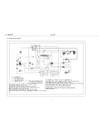
Page 169: ...Appendix 7 6 Air braking schematic diagram...
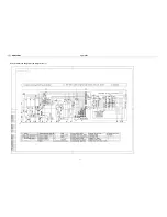
Page 170: ...Appendix 7 7 Electric schematic diagram of the complete car 1...
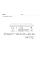
Page 171: ...Appendix 7 7 Electric schematic diagram of the complete car 2...
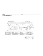
Page 172: ...Appendix 7 7 Electric schematic diagram of the complete car 3...
Page 173: ...Appendix 7 7 Electric schematic diagram of the complete car 4...

