Operation Instruction
3-1
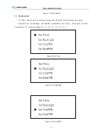
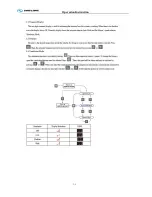
Figure-29 Set MotPPR
Finally press S2 and S3 could increase or decrease MotPPR. After set MotPPR, press S4 two times
return main interface.
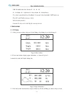
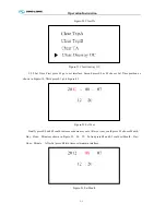
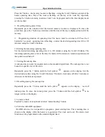
3.2.6 Clear Trip A. First press S1 go to set interface, Second press S2 or S3 choose Clear Trip A
position as shown in Figure-18. Third press S1 clear Trip A and auto return main interface.
3.2.7 Clear Trip B. First press S1 go to set interface, Second press S2 or S3 choose Clear Trip B
position as shown in Figure-19. Third press S1 clear Trip B and auto return main interface.
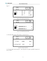
3.2.8 Clear TA. First press S1 go to set interface, Second press S2 or S3 choose Clear TA position as
shown in Figure-20. Third press S1 clear TA and auto return main interface.
3.2.9 Clear One way OC. First press S1 go to set interface, Second press S2 or S3 choose Clear One
way OC position as shown in Figure-21. Third press S1 clear One way OC and auto return main interface.
Appendix
A
ZB271M
Dashboard Pin Definition
Table A Pin Definition
Pin Name
Color
Remark
1 VPP
Red
2 GND
Black
3
WAKE_UP1
Red
Connected to WAKE_UP2 inside
4
CANH1
Yellow
Connected to CANH2 inside
5 CANH2
Yellow
6
CANL1
Green
Connected to CANL2 inside
7 CANL2
Green
8 Empty
9 Empty
10 Empty
11 WAKE_UP2
Red
12 Empty
13 Empty
14 Empty
15 Empty
16 Empty
17 Empty
18 Empty
19 Empty
20 Empty
21 Empty
Summary of Contents for XMQ6900 Series
Page 19: ...Operation Instruction 3 1 Figure 17 Set MotPPR Figure 18 Clear Trip A Figure 19 Clear Trip B...
Page 31: ...Operation Instruction 3 3 CC350 355 series A C Operation...
Page 32: ...Operation Instruction 3 3...
Page 33: ...Operation Instruction 3 3...
Page 34: ...Operation Instruction 3 3...
Page 35: ...Operation Instruction 3 3...
Page 44: ...Operation Instruction 3 4 1 9 Retarder operation...
Page 45: ...Operation Instruction 3 4 Section 1 1 2 1 10 Stopping parking...
Page 49: ...Operation Instruction 3 4 1 14 1 Emergency operation...
Page 50: ...Operation Instruction 3 5 WABCO ABS BASIC INTRODUCTION...
Page 51: ...Operation Instruction 3 5...
Page 52: ...Operation Instruction 3 5...
Page 53: ...Operation Instruction 3 5...
Page 54: ...Operation Instruction 3 5...
Page 55: ...Operation Instruction 3 6 ECAS System Introduction for tourist bus use 1 System introduction...
Page 56: ...Operation Instruction 3 6 3 System function...
Page 57: ...Operation Instruction 3 6...
Page 169: ...Appendix 7 6 Air braking schematic diagram...
Page 170: ...Appendix 7 7 Electric schematic diagram of the complete car 1...
Page 171: ...Appendix 7 7 Electric schematic diagram of the complete car 2...
Page 172: ...Appendix 7 7 Electric schematic diagram of the complete car 3...
Page 173: ...Appendix 7 7 Electric schematic diagram of the complete car 4...

