Operation Instruction
3-19
Relays & Fuses
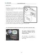
The Relays & Fuses Box always installed in the
compartment of the instrument desk or a tool cabin belong
to front right side panel.
The box integrates 50 chip-type fuses, 20 general and
special relays, and has 8 standby chip type fuses, one fuse
clip, which makes its construction more compact and
function more powerful. It improves design of the past
Relays & Fuses Box , therefore it avoids weakness such as
unreliability and short service life, it applies integrated
circuit and designs 5 special relays: intermittent wiper
relay, turning flasher relay, lower water level warning
controller relay, monitor power relay, brake light failure
warning relay (when power supply voltage is lower than
23V, power supply of acoustic set and monitor is cut off
and will be begin to work again after power supply voltage resumes to normal)
.
The vehicle installed the Relays & Fuses Box in the compartment of instrument desk.
Installation Position
The position of Management Module,
CAN Processor Module, and the
Relays & Fuses Box
They are located in the compartment of
instrument desk. When servicing, may open the
desk cabin gate
Summary of Contents for XMQ6900 Series
Page 19: ...Operation Instruction 3 1 Figure 17 Set MotPPR Figure 18 Clear Trip A Figure 19 Clear Trip B...
Page 31: ...Operation Instruction 3 3 CC350 355 series A C Operation...
Page 32: ...Operation Instruction 3 3...
Page 33: ...Operation Instruction 3 3...
Page 34: ...Operation Instruction 3 3...
Page 35: ...Operation Instruction 3 3...
Page 44: ...Operation Instruction 3 4 1 9 Retarder operation...
Page 45: ...Operation Instruction 3 4 Section 1 1 2 1 10 Stopping parking...
Page 49: ...Operation Instruction 3 4 1 14 1 Emergency operation...
Page 50: ...Operation Instruction 3 5 WABCO ABS BASIC INTRODUCTION...
Page 51: ...Operation Instruction 3 5...
Page 52: ...Operation Instruction 3 5...
Page 53: ...Operation Instruction 3 5...
Page 54: ...Operation Instruction 3 5...
Page 55: ...Operation Instruction 3 6 ECAS System Introduction for tourist bus use 1 System introduction...
Page 56: ...Operation Instruction 3 6 3 System function...
Page 57: ...Operation Instruction 3 6...
Page 169: ...Appendix 7 6 Air braking schematic diagram...
Page 170: ...Appendix 7 7 Electric schematic diagram of the complete car 1...
Page 171: ...Appendix 7 7 Electric schematic diagram of the complete car 2...
Page 172: ...Appendix 7 7 Electric schematic diagram of the complete car 3...
Page 173: ...Appendix 7 7 Electric schematic diagram of the complete car 4...


