Vehicle Starting and Driving
4-10
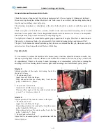
3. Tachometer working order
Indications on tachometer scale:
a.
Green zone – operating range of maximum
performance
b.
Yellow zone – a little high speed range (warning of
engine overspeed )
c.
Red zone – engine overspeed range (risk of
immediate engine damage)
Always observe tachometer while driving the vehicle.
Whenever possible keep engine running within the
economical range.
(
green zone
)
On downgrade, select an adequate gearbox speed and monitor vehicle speed to avoid engine operating in
the danger range (red zone).
When the exhaust-brake is operating on down grades, select an adequate gearbox speed to keep engine
speed within efficient exhaust-brake operation
(
yellow zone
)
.
Always avoid engine over revving (red zone), as engine operation in this speed range can give rise to a
immediate engine damage or seriously jeopardize its durability.
The yellow range with red reticle can be used occasionally when the exhaust-brake needs to be used at its
efficiency limit, however, at risk of engine durability. Therefore, do not operate in this range in a normal
or usual way.
Summary of Contents for XMQ6900 Series
Page 19: ...Operation Instruction 3 1 Figure 17 Set MotPPR Figure 18 Clear Trip A Figure 19 Clear Trip B...
Page 31: ...Operation Instruction 3 3 CC350 355 series A C Operation...
Page 32: ...Operation Instruction 3 3...
Page 33: ...Operation Instruction 3 3...
Page 34: ...Operation Instruction 3 3...
Page 35: ...Operation Instruction 3 3...
Page 44: ...Operation Instruction 3 4 1 9 Retarder operation...
Page 45: ...Operation Instruction 3 4 Section 1 1 2 1 10 Stopping parking...
Page 49: ...Operation Instruction 3 4 1 14 1 Emergency operation...
Page 50: ...Operation Instruction 3 5 WABCO ABS BASIC INTRODUCTION...
Page 51: ...Operation Instruction 3 5...
Page 52: ...Operation Instruction 3 5...
Page 53: ...Operation Instruction 3 5...
Page 54: ...Operation Instruction 3 5...
Page 55: ...Operation Instruction 3 6 ECAS System Introduction for tourist bus use 1 System introduction...
Page 56: ...Operation Instruction 3 6 3 System function...
Page 57: ...Operation Instruction 3 6...
Page 169: ...Appendix 7 6 Air braking schematic diagram...
Page 170: ...Appendix 7 7 Electric schematic diagram of the complete car 1...
Page 171: ...Appendix 7 7 Electric schematic diagram of the complete car 2...
Page 172: ...Appendix 7 7 Electric schematic diagram of the complete car 3...
Page 173: ...Appendix 7 7 Electric schematic diagram of the complete car 4...

