1.35
www.kingslide.com
King Slide reserves the right to alter specifications of all the products without notice. If the entity is different from the illustration, please refer to the entity.
Undermount Slides
1
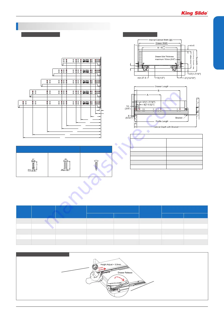
Dimension Specifications
10
1A68F229
1A68F305
1A68F381
1A68F457
1A68F533
37
69
133
165
229
261
357
453
517
Max14(9/16")
10
1A68F229
1A68F305
1A68F381
1A68F457
1A68F533
37
69
133
165
229
261
357
453
517
Max14(9/16")
Item No.
Drawer Length
mm (inch)
Overall Cabinet Depth
mm (inch)
Cabinet Depth With Bracket
mm (inch)
Profile Length
mm (inch)
System Screw Locations
mm (inch)
MAX
MIN
A
B
1A68F229
229 (9")
305 (12")
299 (11-25/32")
266 (10-15/32")
256 (10-1/16")
133 (5-1/4")
229 (9")
1A68F305
305 (12")
381 (15")
369 (14-9/16")
326 (12-7/8")
317 (12-1/2")
165 (6-1/2")
261 (10-1/4")
1A68F381
381 (15")
457 (18")
446 (17-9/16")
403 (15-7/8")
394 (15-1/2")
165 (6-1/2")
357 (14-1/16")
1A68F457
457 (18")
533 (21")
522 (20-9/16")
479 (18-7/8")
470 (18-1/2")
261 (10-1/4")
453 (17-13/16")
1A68F533
533 (21")
610 (24")
598 (23-9/16")
555 (21-7/8")
546 (21-1/2")
261 (10-1/4")
517 (20-3/8")
Fit with American standard 3" cabinet depth system.
Drawer Width Formula
Drawer Side Thickness
mm (inch)
"W" minus
mm (inch)
16 (5/8")
10 (3/8")
15 (19/32")
12 (15/32")
14 (9/16")
14 (9/16")
13 (1/2")
16 (5/8")
12 (15/32")
18 (23/32")
W: Internal Cabinet Width
Example:
Internal Cabinet Width = 457 mm (18")
Drawer Side Thickness = 13 mm (1/2")
Drawer Width = 457 - 16 = 441
mm
= (18") - (5/8") = 17-3/8"
+0
-2
○
X
Chipboard Screws
System Screws
Cabinet Holes Position
Note:
Holes other than those shown may be in the slide member at King Slide's option and may change without notice.
-2.0
+0
Overlay
installation
Inset
installation
Tool-less Height Adjustment :
Simply rotate the wheel at the front bottom of the
drawer to adjust the drawer height
Drawer Removal:
Simply press the front release device
to remove the drawer
Easy Assembly with Front-End Installation
•
Red Dots : Minimum Screw Required
Note: Ensure the slide is parallel to the horizon or tilt to cabinet front
on both sides during installation.
Space Requirement
Summary of Contents for 1A68F
Page 5: ......


