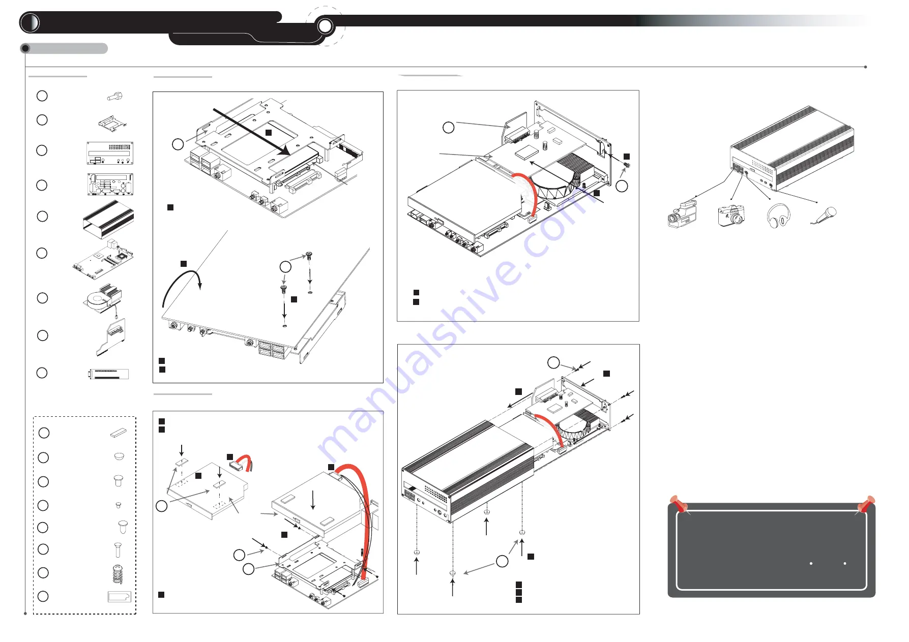
Part List
STEP 1
DVD-ROM Drive Screws (* 5)
Case Screws (* 2)
M
J
EMI Sticker (*2)
Rubber Stand (*4)
L
O
K
Install Slim HDD
STEP 2
Install DVD-ROM Drive
M1675E
CPU Cooler Screws (* 2)
P
Accessory Pack
L
DVD-ROM Drive
Bracket
A
B
C
D
2.5" HDD Screws (* 5)
E
COM/DVI Screws (* 6)
Front Panel
Rear Panel
Case
2
3
180
0
Turnover the Mainboard.
2
3
Q
CPU Cooler Paste (* 1)
T
SIN
K P
AST
E
SIL
ICO
NE
HE
AT
SIN
K P
AST
E
INK
P
AS
INSTALLATION GUIDE
Mainboard
F
B
HDD
1
1
Install HDD attach to Drive Adapter.
**Notice:The HDD's label side is up.
CD-ROM drive
B
J
M
Paste EMI Stickers oo the top of the DVD-ROM drive.
Connecting onboard SATA cable to the DVD-ROM drive.
1
3
2
3
2
1
Tighten DVD-ROM drive with screws to the DVD-ROM
drive braket.
2
CPU Cooler
G
Hardware Installation
Optional DVI-D
Daughter Boards
I
The system uses entire case for
partial heat dissipation, so the
normal operating temperature
of the case is between 40 C ~ 50 C.
Specification is subject to change without notice, it is for reference only.
Tighten HDD with screws to the Mainboard.
4 Lane PCIe
Riser Card
H
WARNING
This equipment has been tested and found to comply with the limits
for a Class B digital device, pursuant to Part 15 of the FCC rules.
These limits are designed to provide reasonable protction against
harmful interference when the equipment is operated in a residential
installation. This equipment generates, uses, and can radiate radio
frequency energy and if not installed and used in accordance with
the instruction manual may cause harmful interference to radio
communications. However, there is no guarantee that interference
will not occur in a particular installation. If this equipment does cause
harmful interference to radio or television reception, which can be
determined by turning the equipment off and on, the user is encouraged
to try to correct the interference by one or more of the following
measures:
* Reorient or relocate the receiving antenna.
* Increase the separation between the equipment and receiver.
* Connect the equipment into an outlet on a circuit different from that to
which the receiver is connected.
* Consult the dealer or an experienced radio TV technician for help.
Notice: The changes or modifications not expressly approved by the
party responsible for compliance could void the user's authority
to operate the equivalent.
Complete System
Install Case
Install mainboard into the case.
1
T
ighten rear panel with screws to the case.
2
Stick the rubber stand.
3
O
K
1
3
2
STEP 3
Install PCI-E Card
Install PCI-E Card into the PCI-E Slot.
1
Tighten PCI-E Card and rear panel with the screw.
.
2
1
4 or 1 Lane PCI-E Card
Note: The length of PCI-E card not longer than 8.5 inch (220mm).
2
N
4 Lane PCI-E Riser Card
H
PCIe Card Fasten Screws (* 1)
N


