background image

PIPING & COMPRESSOR CONTROLS

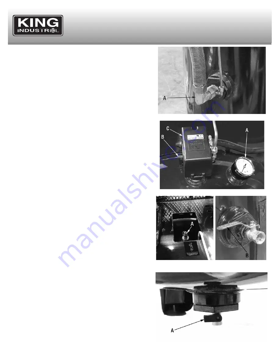
FIGURE 7

FIGURE 8

FIGURE 9

FIGURE 10

ADDITIONAL REGULATORS AND CONTROLS 

 
Since the air tank pressure is usually greater than that which is needed, an 
air pressure regulator should be employed to control the air pressure ahead 
of any individual driven device. An air control unit which combines the       
function of air regulation, moisture and dirt removal should be used.  
 

OPERATION CONTROLS 


CHECK VALVE (A) FIG.7. 

When the air compressor is operating, the check 

valve is “open”, allowing compressed air to enter the air tank. When the air 
compressor reaches its “Cut-Out” pressure, the check valve “closes”,       
allowing air pressure to remain inside the air tank. 
 

TANK PRESSURE GAUGE (A) FIG. 8. 

The tank pressure gauge indicates 

the reserve air pressure in the tank. 
 

ON/AUTO-OFF SWITCH (B) FIG.8. 

Turn this switch ON to provide power to 

the automatic pressure switch and OFF to remove power at the end of each 
use. 
 

PRESSURE SWITCH (C) FIG.8. 

The pressure switch automatically starts the 

motor when the tank pressure drops below the factory set “Cut-In” pressure. 
It also stops the motor when the air tank pressure reaches the factory set 
“Cut-Out” pressure. 

 
ASME SAFETY VALVE (A) FIG. 9.

 If the pressure switch does not shut off 

the air compressor at its cutout pressure setting, the safety valve will protect 
against high pressure by “popping out” at its factory set pressure (slightly 
higher than the pressure switch cut-out setting). 
 

WARNING!

: If the safety valve does not work properly, over pressurization 

may occur, causing air tank rupture or an explosion. Daily pull the ring on the 
safety valve to make sure that the safety valve operates freely. If the valve is 
stuck or does not operate smoothly, it must be replaced with the same ASME 
type of valve. 

 
BALL VALVE OUTLET PRESSURE LEVER (B) FIG. 9.

 This lever controls 

the amount of pressurized air in the air delivery piping system.  
 

DRAIN VALVE (A) FIG.10.

 The drain valve is located at the base of the air 

tank and is used to drain condensation at the end of each use. Turn drain 
valve counterclockwise to open (no pressure build-up) or clockwise to close 
it (permits pressure build-up).

Summary of Contents for KC-7180V3-MS

Page 1: ...INSTRUCTION MANUAL MODEL KC 7180V3 MS COPYRIGHT 2020 ALL RIGHTS RESERVED BY KING CANADA TOOLS INC HIGH OUTPUT STATIONARY 7 5 PEAK HP 80 GALLON AIR COMPRESSOR ...

Page 2: ...e abuse normal wear and tear negligence or accidents repairs done by an unauthorized service center alterations and lack of maintenance King Canada shall in no event be liable for death injuries to persons or property or for incidental special or consequential damages arising from the use of our products To take advantage of this limited warranty return the product at your expense together with yo...

Page 3: ... exposed metal such as the compressor head or outlet tubes can result in serious burns HOW TO PREVENT IT Never touch any exposed metal parts on compressor during or immediately after operation The compressor will remain hot several minutes after use Do not reach around protective shrouds or attempt maintenance until the compressor has cooled down completely RISK OF PROPERTY DAMAGE WHEN TRANSPORTIN...

Page 4: ... magnetic switch See grounding information below Warning Do not attempt to hard wire this compressor yourself unless you are a qualified electrician Overheating short circuiting and fire damage will result from inadequate wiring Electrical wiring codes local or provincial may differ from area to area Source wiring plug and protector must be rated for at least the amperage and voltage indicated on ...

Page 5: ...g 3 is in the OFF position 2 Make sure the compressor is properly wired to electrical source and grounded if a power cord was installed plug the power cord into a grounded 240V branch circuit receptacle 3 Make sure the oil level in the crankcase reaches the centre dot of the oil sight glass A Fig 4 refer to maintenance section for instructions on fill the crankcase with oil 4 Open the drain valve ...

Page 6: ...ch automatically starts the motor when the tank pressure drops below the factory set Cut In pressure It also stops the motor when the air tank pressure reaches the factory set Cut Out pressure ASME SAFETY VALVE A FIG 9 If the pressure switch does not shut off the air compressor at its cutout pressure setting the safety valve will protect against high pressure by popping out at its factory set pres...

Page 7: ... in the centre of the red dot of oil sight glass 2 Drain condensation from tank 3 Check for any unusual noise or vibration 4 Be sure all nuts and bolts are tight Monthly 1 Inspect air system for leaks by applying soapy water to all joints Tighten those joints if leakage is observed Initial oil change must be done after the first 100 hours 1 Once initial oil change is done after 100 hours of operat...

Page 8: ... Crankcase breather valve malfunction Worn piston rings Piston rings not seated CORRECTIVE ACTION Check voltage or eliminate extension cord or reset Check wiring connections Wait for motor to cool then press the reset button restart Drain tank of air pressure Check valve manually by pulling If condition persists replace Close drain cock Clean or replace as necessary Replace check valve Check for p...

Reviews: