background image

4

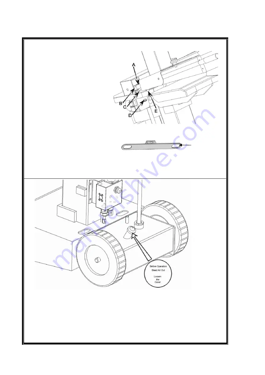
10 . Assembly of operation Handle with Guard

Put the head of operation

handle(A) into the hole

for flat steel

see below

inside the cover(B).

Put bolt M12x15(E)into

The hole (C), then fix it with nut

M12(D).

Flat Steel

Attention

: The operation handle guard should be assembled by trained

professional people or engineers.

11.

Bleed the air out of the Hydraulic system before starting the log splitter.
The Cover of the hydraulic oil tank should be loosened by some rotations
until air can go in and out of the oil tank smoothly.
Air flow thru the oil tank filler should be detectable during the operations.
Before moving the log splitter, make sure the cover of the oil tank is
Tightened to avoid oil leaking from this point.

Summary of Contents for LS10TG

Page 1: ...Instruction Manual For Hydraulic Log Splitter LS10TG FOR YOUR SAFETY Read and understand the entire manual before operating machine Save this manual for future reference ...

Page 2: ...lve 4 Pump 6 Wheel 10 Oil Tank Cover 11 Oil Tank 19 Square Pipe 23 Ram Travel adjusting Rod 27 Adjustable Log Holder 28 Log Holder Adjusting Knob 29 Operation handle 30 Control Lever Guard 32 Moving handle 33 Cover 35 Working table ...

Page 3: ...3 4 5 6 7 8 9 ...

Page 4: ... be assembled by trained professional people or engineers 11 Bleed the air out of the Hydraulic system before starting the log splitter The Cover of the hydraulic oil tank should be loosened by some rotations until air can go in and out of the oil tank smoothly Air flow thru the oil tank filler should be detectable during the operations Before moving the log splitter make sure the cover of the oil...

Page 5: ...e and repair instructions contained in this manual Allow only adults to operate maintain the log splitter after they have received sufficient training and have made themselves familiar with the machine Make sure that full compliance is assured at all times with the general safety and health rules on the workplace as well as the applicable local traffic rules No one under the age of 18 should be al...

Page 6: ...lace with sufficient clearance for proper operation of the machine as well as or safe handling of the split logs and eventual ancillary tools and equipment To be operated by one person only PREVENT FIRES Do not smoke or have open flames when operating or refilling the log splitter Never operate the log splitter near a flame or spark Oil is flammable and can exploded PROTECT YOUR HANDS When the ram...

Page 7: ...lf unless you are a professional engineer Otherwise the self assembling may lead to some dangers as below 1 Oil leak 3 gasoline engine pump damage 2 No pressure 4 pressure is too big for cylinder endurance etc 3 Operating instructions 3 1 Hand guards assembly Uncrate and assemble the special hand guards on the hand control levers before first use and installation The two hand control levers must b...

Page 8: ...position when the hand pressure is released 3 4 Start up Before first use make sure that the log splitter is in good conditions and that no visual damages are there Check all hydraulic hoses fittings and coupling and to detect and repair eventual oil leaks Make sure that all safeties and protections are duly assembled on the machine Do not attempt to remove or by pass these safeties Make sure the ...

Page 9: ...ble The ram travel is reduced by an equivalent stroke length as the pulled up rod length Once the rod is pulled sufficiently up to obtain the desired ram stroke tight the wing nut or knob back to the original torque Now completing a shorter travel than the original full stroke Later ram travel adjustments to the original full stroke length can be repeated at all times by simply releasing the wing ...

Page 10: ... the oil level is too low Starting The Enging 1 Open The Gas Valve By Moving To The Right Close The Choke By Moving it To The Left Note If The Engine Is Already Hot It Is Not Necessary To Close The Choke Open The Throttle By Moving To The Left Rabbit Symbol See Bottom Photo 2 Turn The Engine Switch To The On Position 3 Gently Pull The Recoil Starter Handle Until It Engages Then Pull It All The Way...

Page 11: ...ith green dry branches may burst under wedge pressure Make sure to shut the gasoline engine off before leaving the area at work end 3 11 Log Clearing procedure Always set logs firmly on the work table make sure logs will not twist rock or slip while being split Do not place log across the log splitter for splitting not attempt to split 2 pieces of logs at the same time to avoid injury Depending on...

Page 12: ...p Failure to maintain due oil or level may cause poor running and irregular splitter operation very rough back forth or up down motions as well as major pump damages Please schedule your first oil change after approximately 25 30 operation hours and later ones after each 50operation hours or once a year The oil drain plug is location on the bottom tank side while the filler cap is on the upper rig...

Page 13: ...m casing and the guide sliding pads are likely to be worn out if so replace them with brand new ones 6 Technicai specifications Model number LS10TG Log capacity 550 820 1040mm Min log diameter 70mm Max log diameter 350mm Tank capacity 4 5L Splitting force 10T Engine power output 4 8KW Total height raised ram 1535mm Total height retracted ram 1055mm Width 400mm Length 845mm Weight 125 135KGS The ac...

Page 14: ...14 Hydraulic Diagram ...

Page 15: ... result into serious injures to the operator or the other person around the workplace Keep hands and fingers clear at all time Many log splitting accidents happen on the return portion of the stroke 8 Trouble shooting chart Type of malfunction Possible origins of the problem Solutions When the control hands is Pushed down The wedge Doesn t tower Oil level is too low Fill oil in Ram won t retract S...

Page 16: ...16 ...

Page 17: ...17 ...

Page 18: ...TM 03 22 Φ28 1 1 13 Seal ringΦ28 1 14 Dustproof ringΦ28 1 1 15 Hydraulic cylinder column 1 1 16 StopperΦ70 1 1 17 StopperΦ65 1 2 Gasoline engine 1 3 Direction exchanging valve assembly Direction exchangin g valve 3 1 M6x45 inner six angle Bolt 2 3 2 Valve front cover 1 3 3 Spring Ø3x45 1 3 4 M6x15 inner six angle bolt 1 3 5 Spring bush 1 3 6 o ring Ø22x2 4 3 3 7 G3 8 xM18 straight angle curly head...

Page 19: ...nk seat 1 12 Main vertical pipe 1 13 Oil filter assembly 1 14 High pressure oil pipe assembly 1 15 Oil pipe assembly 1 16 Lower ram rod 1 17 Pin Φ25 1 18 Sliding plastic pad 4 19 Square pipe 1 20 Upper cover 1 21 Plug 1 22 Bolt m8x20 1 23 Upper ram rod 1 24 Handle pull seat 1 25 Knob 1 26 Left operating handle guard 1 27 Side clamp vice 2 28 Clamping vice knob 2 29 Handle 2 30 Right operating hand...

Reviews: