background image


3

Preparation
Preparación

Preparação

Przygotowanie


5

 57


31

 83

Assembly 
Montaje

Montagem


13

 65


39

 91

Cuidados y Mantenimiento


25

 77


51

 103

Summary of Contents for 3663602705284

Page 1: ...ONS JOB INFO VERSION PID SUME10936 Agency job 00001 Product Description FPLMP450BS HP 2 Petrol Lawnmower 125cc IM A5 v1 Lawnmower IM Brand Mac Allister Brand Contact jennifer bliss kingfisher com Barcode 3663602705284 Vendor Sumec No of new line drawings xx Page size A5 No of printed pages 112 2 3 R 5 6 7 8 12 09 17 INITIALS 26 09 17 TjB 13 10 17 DLS 13 10 17 DLS 00 00 17 INITIALS 00 00 17 INITIALS...

Page 2: ...3 Preparation Preparación Preparação Przygotowanie 5 57 31 83 Assembly Montaje Montagem 13 65 39 91 Cuidados y Mantenimiento 25 77 51 103 ...

Page 3: ...Sroduktu i achoZaü na Sr ys áoĞü Estas instrucciones son para su propia seguridad Léalas atentamente antes de usar el producto y guárdelas para referencia futura Estas instruções são para sua segurança Leia as atentamente antes de utilizar e guarde as para futura referência x2 Unleaded Petrol SAE10W 30 Engine Oil 1 2 3 4 5 6 7 9 8 8a 10 11 12 13 14 16 17 24 25 15 22 5 20 21 18 19 23b 23a 23c 23d 2...

Page 4: ...rior 2 Barra de freno 3 Cable de freno 4 Pernos de cuello cuadrado con cabeza redonda M8X45 2 unidades 5 Ruedecilla de bloqueo con tuerca M8 4 unidades 6 Barra del manillar inferior 7 Sujetacables 8 Depósito de combustible a Tapón del depósito de combustible 9 Rejillas de ventilación 10 Cebador 11 Carcasa del ltro de aire a Filtro b Cubierta c Cierre 12 Conector de la bujía 13 Rueda 14 Silenciador...

Page 5: ...NG Refuel outdoors only and do not smoke while refuelling Add fuel before starting the engine Never remove the cap of the fuel tank or add petrol while the engine is running or when the engine is hot If petrol is spilled do not attempt to start the engine but move the product away from the area of spillage and avoid creating any source of ignition until petrol vapours have dissipated Replace all f...

Page 6: ...ft only the part which is away from the operator 22 Do not start the engine when standing in front of the discharge chute 23 Do not put hands or feet near or under rotating parts Keep clear of the discharge opening at all times 24 Never pick up or carry a product while the engine is running 25 Stop the engine and disconnect the spark plug connector make sure that all moving parts have come to a co...

Page 7: ...poisoning and explosion 5 Avoid skin contact with petrol 6 Do not eat or drink while you are refuelling the product If you have swallowed petrol or oil or if petrol or oil has got into your eyes then seek medical advice immediately 7 Close the tank lid immediately after lling the tank Make sure that it is properly closed 8 Never use the product without an air lter 06 Vibration and noise reduction ...

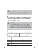
Page 8: ...ty damage caused by Àying objects 4 Burns if touching hot surfaces WARNING This product produces an electromagnetic eld during operation This may under some circumstances cause interference with active or passive medical implants To reduce the risk of serious or fatal injury we recommend persons with medical implants to consult their doctor and the medical implant manufacturer before operating thi...

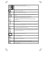
Page 9: ...a around the product and in the vicinity of Àammable materials Risk of re Àammable materials Hot surface do not touch High temperatures on the product s surfaces and structural parts that could cause burns if they are touched The product can also stay hot for a longer period of time after operation This product produces noxious exhaust fumes If the product is used improperly these fumes can lead t...

Page 10: ... HANDS and FEET AWAY Keep hands and feet away Cutting device continues to rotate after the product is switched off Wait until all machine components have completely stopped before touching the product Pay special attention when working on the cutting device Objects thrown by the product could hit the user or other bystanders Always ensure that other people and pets remain at a safe distance from t...

Page 11: ...evel Sound pressure level at operator s position LpA 85 1 dB A Uncertainty K 3 dB A Sound power level LWA 91 6 dB A Uncertainty K 0 85 dB A Guaranteed sound power level L acc to 2000 14 EC amended by 2005 88 EC 96 dB A Vibration Level Hand arm vibration ahw 6 5 m s2 Uncertainty K 1 5 m s2 The sound values have been determined according to noise test code given in EN ISO 5395 2 using the basic stan...

Page 12: ...le surface 2 Remove all packing materials and shipping devices if applicable 3 Make sure the delivery contents are complete and free of any damage If you nd that parts are missing or show damage do not use the product but contact your dealer Using an incomplete or damaged product represents a hazard to people and property 4 Ensure that you have all the accessories and tools needed for assembly and...

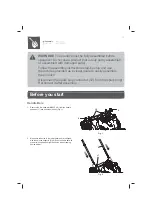
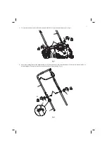
Page 13: ...visual guide to easily assemble the product Disconnect the spark plug connector 12 from the spark plug Reconnect it after assembly Before you start Handle Bars 1 Remove the Arc head blot M8X35 18 from the handle supports 17 and keep them handy Fig 1 5 18 5 Fig 1 2 Make sure the holes in the lower handle bar are aligned with those in the supports Fig 2 Ensure handle bar with starter coil loop tted ...

Page 14: ... to the handle supports 17 Fig 3 18 5 5 6 Fig 3 4 Align the mounting holes of the upper handle bar 1 with the ones on the lower handle bar 6 Ensure the rope guide 21 is properly aligned Secure the connection with the knobs 5 and bolts 4 Fig 4 1 21 5 5 6 21 4 Fig 4 ...

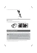
Page 15: ...ne Before operation it is necessary to add proper fuel and engine oil separately WARNING This product contains an instruction manual of the engine Service the engine with proper petrol and engine oil as instructed in the separate engine handbook 26 It is important to read and understand these instructions about the engine and the equipment SAVE THESE DOCUMENTS FOR FUTURE REFERENCE 1 Place the prod...

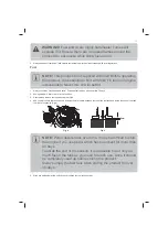
Page 16: ...2 Avoid getting dirt dust or water in the fuel tank 3 Unscrew and remove the fuel tank cap 8a Fig 8 4 Add correct fuel into the tank Leave a minimum 5mm of space between the top of the fuel tank and inside the edge of the tank to allow for expansion Fig 9 5mm 8a 15 Fig 8 Fig 9 NOTE Petrol deteriorates over time It may be dif cult to start the engine if you use petrol which has been kept for more t...

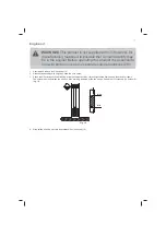
Page 17: ...ook 26 1 Unscrew and remove the oil tank cap 15 2 Gradually add good quality engine oil Allow the oil to settle 3 Check the oil level frequently while lling Wipe the oil dipstick clean re t and tighten the ller cap and then remove it again The oil level must be between the µmin and µmax marking indicated by the two arrows Add more oil if necessary Do not over ll g 10 Max Min Fig 10 4 Wipe spilled ...

Page 18: ...power output of 1 8kW 1 The product is intended for mowing grass in domestic gardens only It must not be used to mow unusually high dry or wet grass e g pasture grass for shredding leaves or mulching 2 For safety reasons it is essential to read the entire instruction manual before rst operation and to observe all the instructions therein 3 This product is intended for private domestic use not only...

Page 19: ... the brake bar 2 towards the Upper handle bar 1 2 Slowly pull on the recoil starter handle 22 Fig 12 and t it into the rope guide 21 on the right hand side of the lower handle 6 during operation Fig 13 Do not remove the rope from the rope guide when starting the engine 22 Fig 12 1 2 21 Fig 13 WARNING Never twist the starter cord around your hand Only pull on the handle WARNING Do not suddenly rele...

Page 20: ...mpty the grass clippings onto a compost heap 5 Re t the grass catcher 20 to the product WARNING Do not attempt to use the product without the grass catcher attached when collecting grass danger of Àying objects Switch the engine off and wait until the blade has come to a complete stop before removing the grass catcher 05 Cutting height adjustment Adjust the cutting height according to the needs of...

Page 21: ...es and attachments are properly xed 3 Check the fuel and oil level re ll if necessary 4 Always push the product on its handle Use the self propelling function if required Keep the handle dry and free from lubricant to ensure safe support 5 Ensure that the air vents are always unobstructed and clear Clean them if necessary with a soft brush Blocked air vents may lead to overheating and damage the p...

Page 22: ... 3 to 5 times for cold rst starting only Pull and hold brake bar Pull recoil starter sharply repeat until engine starts Operate 1 Press the primer 10 three to ve times Fig 16 step 1 when engine is cold Once engine has been run and is hot there is no need to push primer 2 Stand behind the handle 1 3 Pull the brake bar 2 against the handle 1 and hold it in position with one hand Fig 17 step 2 4 Pull...

Page 23: ...tion handbook Fig A is the de ned starting position User should start the engine behind the lever DO NOT start the engine standing beside the deck as Fig B Fig A Fig B Stopping Release brake bar Empty fuel tank Clean and maintain Store Release the brake bar 2 to stop the engine and blade Fig 18 ...

Page 24: ...ost effective pattern for mowing lawns is straight lines along one of the sides This will keep the rows even and ensures that all the lawn is cut without missing any spots Fig 19 Fig 19 5 Circle around Àower beds When reaching a Àower bed in the middle of the lawn cut around or two around the circumference of the bed 6 Pay special attention when changing direction 7 Empty the grass catcher regular...

Page 25: ...ormed by a quali ed specialist Product maintenance Before and after each use check the product and accessories such as application tools for wear and damage If required exchange them for new ones as described in this instruction manual Observe the technical requirements Underbody and cutting device WARNING Wear protective gloves when working on the cutting device and close to it Use proper tools t...

Page 26: ... Fig 20 23a 23b 23c 23 23d 23e Fig 20 5 Replace the cutting device with a new one of the same type Slide the pin 23b into the slot on the spindle 23a 23c support 23d locking Àange 23e and hex bolt 23f Tighten the hex bolt clockwise with 40 N m min 50 N m max to ensure safe operation of your product NOTE Replace this cutting device after 50 hours mowing or 2 years whichever is sooner regardless of ...

Page 27: ...11 Repair This product does not contain any parts that can be repaired by the consumer Contact an authorised service centre or similarly quali ed person to have it checked and repaired Storage 1 Switch the product off and disconnect the spark plug connector 2 Clean the product as described above 3 Store the product and its accessories in a dry frost free place 4 Always store the product in a place...

Page 28: ...park plug gap is incorrect 1 9 Carburettor is Àooded with fuel 1 10 Faulty ignition module 1 4 Attach properly 1 5 Move throttle lever to correct position 1 6 Clean air lter 1 7 Tighten spark plug 20 N m 1 8 Set gap between electrodes at 0 457 0 61mm 1 9 Remove air lter and pull recoil starter handle continuously until carburettor clears itself and install air lter 1 10 Contact the service agent 2...

Page 29: ...otentially recyclable and do not therefore belong in your household rubbish You are requested to assist us and our contribution to saving resources and protecting the environment by handing in this product at an equipped collection centre if there is one available 2 Petrol oil used oil a mixture of oil and petrol and objects soiled with oil e g cleaning cloths do not belong in the household rubbis...

Page 30: ...09 The Outdoor Noise Directive 2000 14 EC 2005 88 EC Measured Sound Power Level 91 6 dB A Guaranteed Sound Power Level 96 dB A EN ISO 3744 1995 ISO 11094 1991 GB 1067 6452 18 Issue 1 Test report No SHES180700812361 Conformity assessment procedures Annex VI of the directive Unit 2 Easter Court Europa Boulevard Warrington Cheshier WA5 7ZB United Kingdom The Regulation of Non Road Mobile Machinery Em...

Reviews: