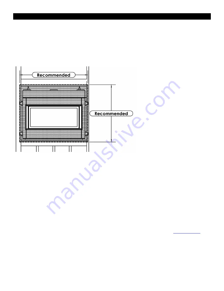
Recommendations for Finishing of Clean View Linear Products
When finishing the wall around the fireplace, it is critical that the wall covering be fastened properly. It is acceptable to
pre-drill holes and use self-tapping screws which may be used to fasten a backer for tile, marble, etc. Screws being
installed through non-combustible board should be self-tapping type with a maximum length of 2 inches. Wall covering
fasteners, such as screws or nails, are not permitted in some locations. Do not drill or install longer screws which may
penetrate into the lower cover panel area as this may damage internal components.
Only
non-combustible
materials may be used over the face of the appliance.
We recommend that CONCRETE BOARD (non-combustible material) be tied in to the entire perimeter of the fireplace for
durability.
Finishing Recommendations
(Obtained from professional construction contractors and finishers):
Frame unit with metal studs (minimum 20 gauge).
Wooden studs may be used, but may cause drywall screws to pop
or pull due to wood studs drying out.
Minimum of 1/2” CONCRETE BOARD cement board (this
non-combustible
panel is ULC listed as a wall shield/floor
protector) and fasten to the entire perimeter framing.
Use fiberglass (mesh) tape for all joints in area of the fireplace.
Use Yellow joint mud (contains high amounts of glue) – two coats, finishing with one coat of green topping mud, sand
and prep for painting.
If not using a surround, a metal “L” Trim may be used to finish perimeter of CONCRETE BOARD.
Refer to the following website for more information on using CONCRETE BOARD Cement Board:
www.cgcinc.com
OTHER NOTES:
-
A full single shee
t of non-combustible board (no joints) above the unit is recommended if possible.
-It is preferred to attach the non-combustible board to
framing only
and not directly to the unit to allow for expansion and
contraction during normal operation.
-Lighter colored painted surfaces may discolor due to heat exposure.
9
Summary of Contents for ZDV3318 Series
Page 31: ...Gas Conversion for Modulator PART C WARNING WARNING 31 ...
Page 35: ...Configuration 1 Basic manual HI LO and manual ON OFF capabilities 35 ...
Page 36: ...Receiver Module 584 523 521 221 1001 P221SI Receiver Module 584 523 521 221 1001 P221SI 36 ...
Page 43: ...Proflame 2 Remote Control 43 ...
Page 45: ...45 ...


