background image

12

Installation

Kingston Technology Company

DE90i-S, Rev. A00

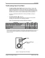
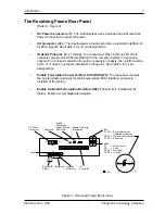
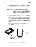
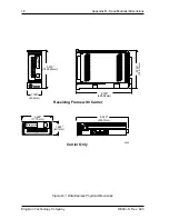
Figure 8:  Data Express Receiving Frame Mounting Holes

4.

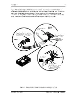
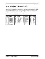
To select the Data Express unit ID remotely through the computer system or
external expansion chassis, the appropriate cable from the system must be
connected to the ID select connector (J4) on the rear of the receiving frame as
shown in Figures 5 and 6.

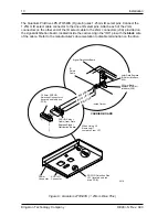
IMPORTANT NOTE: In order to use remote ID selection from a computer or

expansion chassis, a three-wire connector must be connected
from the computer or expansion chassis to the ID0, ID1, and
ID2 pins of J4 of the receiving frame mother board as shown in
Figures 5 and 6. No ID jumpers are required for this type of
configuration. For on board ID selection, use the appropriate
jumpers on J4 as shown in Figure 7.

5.

With the drive carrier locked in place inside the receiving frame, install the Data
Express into the 5.25” drive opening in the computer or expansion chassis. Use
the appropriate guides to position the Data Express, and fasten it into place
with the four 6-32 x 1/4” screws provided. Figure 8 illustrates the location of the
mounting holes. Mounting holes are provided on each side and the bottom of
the receiving frame to accommodate a variety of mounting configurations. Use
the mounting holes which best suit the computer or expansion chassis
configuration. Note that bottom mounting holes require self tapping screws (not
provided).

6.

Adjust the front of the receiving frame so the carrier slides freely in and out on
the receiving frame guides. The position of adjoining peripheral units may
require adjustment.

0415

A
B
C

Receiving Frame
Side Mounting Holes
6-32 x 1/4" Screws
Provided (4 Plcs)

Receiving Frame
Mounting Holes.
Self Tapping Screws Not
Provided (4 Plcs)

Bottom Side of
Receiving Frame

Summary of Contents for DATA EXPRESS DE90

Page 1: ...Kingston Technology DE90 DATA EXPRESS Removable 8 Bit Single Ended SCSI Drive Enclosure...

Page 2: ...Technology Company 17600 Newhope Street Fountain Valley CA 92708 9885 Phone 714 438 1850 Fax 714 438 1847 Kingston Technology DE90 DATA EXPRESS Removable 8 Bit Single Ended SCSI Drive Enclosure Instal...

Page 3: ...prepaid and insured to your local authorized Kingstondealerordistributor ortotheKingstonfactoryservicecenterlocatedat17600NewhopeStreet Fountain Valley California 92708 U S A You must include the prod...

Page 4: ...eiving Frame and Carrier 1 Figure 2 Receiving Frame Front Panel 2 Figure 3 Receiving Frame Rear View 3 Figure 4 Drive Installation Assembly 8 Figure 5 Typical SCSI ID Select Connections 2mm Drive Pins...

Page 5: ...iv Kingston Technology Company DE90i S Rev A00...

Page 6: ...Data Express equipped computer or expansion chassis and also provides the ability to secure sensitive data by removing and storing the drive safely for future use Figure 1 DE90 Receiving Frame and Ca...

Page 7: ...receiving frame front panel provide important operating information based on the following conditions Table 1 Receiving Frame Front Panel Indicator Conditions Figure 2 Receiving Frame Front Panel COND...

Page 8: ...t ID must be set to 0 or open no jumpers installed on these pins See Table 3 for J4 pin assignments Enable Termination Power To From SCSI BUS W1 The rear panel contains the bus terminators active for...

Page 9: ...cted before and during the packing procedure at the factory Bent or broken connectors or evidence of other physical damage to the Data Express should be reported to the carrier immediately If evidence...

Page 10: ...labels and record the numbers in the spaces provided below Receiving Frame Device Carrier Table 2 DE90 Shipment Contents One Kingston Data Express SCSI System Part Number Quantity Disk Carrier subasse...

Page 11: ...6 Introduction Kingston Technology Company DE90i S Rev A00...

Page 12: ...lugs in this area The SCSI ID cable will be installed into this section of the drive 5 SCSI ID Cable The Data Express carrier is supplied with one 1 three wire cable This cable is used for remote ID s...

Page 13: ...signal distribution board See Figures 5 and 6 for the location of the ID select interface connector Installation 1 Attach the I O interface cable from the rear distribution board of the Data Express c...

Page 14: ...efer to the manufacturer s documentation to disable termination on the drive Figure 5 Typical SCSI ID Select Connections 2mm Drive Pins 0412 Signal Distribution Board ID Select Cable Red ID2 Brown ID1...

Page 15: ...the cable Refer to the manufacturer s documentation to disable termination on the drive 0416 SCSI ID Select Cable from Data Express Signal Distribution Board 1 25mm SCSI ID Selection Connector J5 loc...

Page 16: ...lacing jumpers on the appropriate J4 pins Refer to Figure 7 and to Table 3 for additional information Table 3 Receiving Frame Mother Board Connector J4 Pin Configuration Pin 1 RESERVED Pin 11 RESERVED...

Page 17: ...he drive carrier locked in place inside the receiving frame install the Data Express into the 5 25 drive opening in the computer or expansion chassis Use the appropriate guides to position the Data Ex...

Page 18: ...connector on the Data Express receiving frame Refer to Figure 3 for the Data Express receiving frame power connector location 10 Replace any expansion boards that may have been removed earlier Replace...

Page 19: ...pen Pin 29 can be used for Synchronized Spindle operation Pin 26 is reserved for terminator resistor power source Table 4 SCSI Interface Connector J2 Pin Assignments Pin Signal Pin Signal Pin Signal P...

Page 20: ...me Note that the pawl is in an upright position Insert the key into the lock Skip this step if the key is already fixed to the lock 2 Rotate the key 90 degrees counter clockwise so that the pawl is vi...

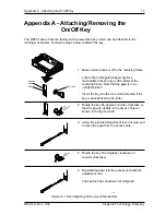
Page 21: ...16 Appendix A Attaching the On Off Key Kingston Technology Company DE90i S Rev A00...

Page 22: ...o 80 10 to 90 Altitude 1000 to 50 000 ft 1000 to 50 000 ft 304m to 15240m 304m to 15240m Shock 2 10g 60g 1 Non condensing with maximum Gradient of 10 per hour 2 11 msec Pulse Width 1 2 Sine Wave Physi...

Page 23: ...Company DE90i S Rev A00 Receiving Frame with Carrier Carrier Only 0406 1 700 43 2mm 5 875 149 225mm K ingston 8 700 220 98mm 8 020 203 7mm 1 680 42 7mm 4 625 117 5mm Kingston Data Express Data Expres...

Page 24: ...allation instructions Everyone at Kingston Technology is working toward the goal of providing you the highest quality most cost effective products available on the market and we need your comments to...

Page 25: ...ND STAPLE SHUT CUT ALONG THIS LINE FROM BOTTOM TO TOP OF PAGE BUSINESS REPLY MAIL POSTAGE WILL BE PAID BY ADDRESSEE NO POSTAGE NECESSARY IF MAILED IN THE UNITED STATES FIRST CLASS MAIL PERMIT NO 10686...

Reviews: