KINOVA
®
Gen3 Ultra lightweight robot
User Guide
46
Note:
The printed circuit board (PCB) of the interface module is partially covered with a touch
shield with holes to expose only the output connectors - 10-pin spring loaded connector, 20-pin
user expansion connector, and Kinova internal end effector interface.
Note:
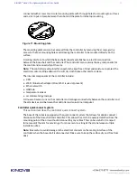
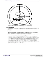
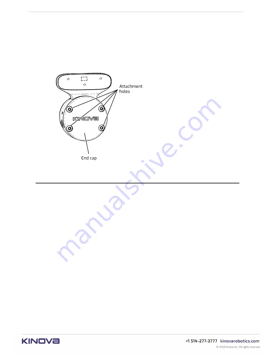
When there is no end effector present, it is recommended to place an end cap over
the face of the interface module. Kinova provides an end cap with the robot. This end cap is
attached to the interface with screws using the mounting holes on the interface. The end cap
needs to be removed to attach an end effector to the robot.
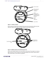
Figure 19: End cap
Vision module
This section describes the Vision module.
The Vision module is a module provided by Kinova to enable robotic computer vision
applications.
The Vision module is mounted on the top side of the Interconnect module. A housing containing
sensors protrudes from the top of the Interconnect module. The sensors are contained on the
front face of the housing, facing out parallel to the axis of the last actuator.
The Vision module is used to capture and stream image data captured looking in the direction
the end of the arm / end effector is pointed. The Vision module includes both a 2D RGB camera
(
Omnivision OV5640
) and a 3D stereo depth sensor (
Intel® RealSense™ Depth Module D410
).
Together, the two cameras allow the capture of RGBD (color and depth) data. Both camera
sensors can be configured using the
KINOVA
®
KORTEX™
VisionConfig
interface.
Performance for the Vision module depth sensor may be degraded at temperatures below
0
°
C
. For more details, please
consult the depth sensor
data sheet
.
The color and depth sensors data streams are made accessible to developers through a
computer with a connection to the robot. For more information on accessing these data streams
programatically, see
here
.

