KINOVA
®
Gen3 Ultra lightweight robot
User Guide
60
Reference design package
A reference design package is available on the Kinova website.
www.kinovarobotics.com/
knowledge-hub/technical-resources
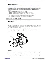
The package includes several useful files to help you with building an end effector. You may use
these files as is or as a starting point to design your own end effector. The package contents
include:
• STL file of the mechanical interface, for 3D-printing
• STEP file and PDF drawing of the mechanical interface, for machining
• STEP file of the Kinova breakout PCB for integration into CAD programs
• KR13933.ASY file which directs the assembly of the PCB (including the BOM)
• KR13933.PCB which directs the PCB fabrication (including Gerber files)
• KR13933.SCH which includes the circuit board schematic diagrams
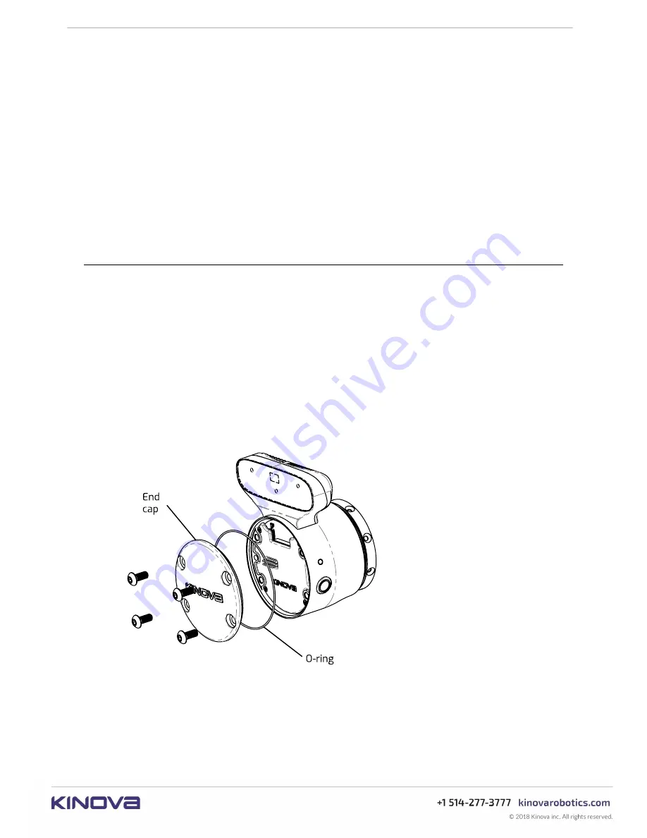
Remove end cap from Interface module
This section describes how to remove the end cap from the Interface module.
Before you begin
You will need a 3 mm hex key.
About this task
The robot ships originally with an end cap over the interface. Attaching an end effector to
the robot requires removing the end cap first. Removing the end cap exposes expansion
and end-effector connection points.
When removing the end cap, there is an O-ring exposed which
must be conserved
. The O-ring
is used to provide protection against water ingress and EMI at the junction between the robot
interface and the end effector.
Procedure
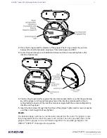
1.
The end cap is held onto the robot interface using four M5 button head cap screws. Using a 3
mm hex key, remove the screws and preserve the screws.
2.
Remove the end cap, and set aside with the screws.
3.
You will see an O-ring on removing the end cap. The O-ring will be needed when attaching an
end effector.


