Installation and initial operation
26
01.04.2020
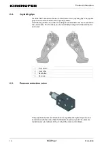
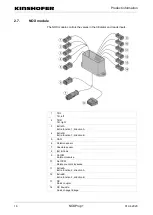
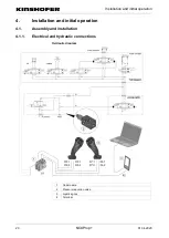
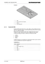
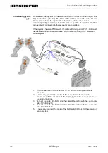
As standard, the joysticks are delivered each with 2 rollers front and rear (R1 and
R3) and 7 buttons (S3 – S9). The buttons S6 and S9 as well as the rollers R1 and
R3 are connected at the input of the cab module. The functions can be
individually configured at the terminal for each user profile. The additional buttons
can be directly connected to the excavator control system.
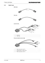
If the joysticks have an FNR switch, the cable with designation PS1 – PS4 must
likewise be connected with a suitable plug connection (PS5) to the excavator
control system.
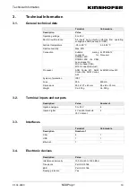
1. Trim the cables for buttons S3, S4, S5, S7 and S8 directly at the cable
connector.
2. If necessary, connect the cables to the excavator control system in
accordance with the allocation of the original joysticks. To do so, measure out
the original joysticks.
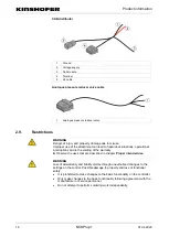
3. Connect the cable of roller R1 and the cable of button S6 with the cab module
cable SVAB 166200.
4. Connect the cable of roller R3 and the cable of button S9 with the cab module
cable SVAB 166400.
5. If necessary, connect the cable of the FNR switch (PS1–4) to the excavator
control system.
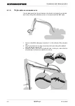
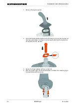
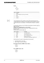
Connecting joystick
grips

