
Installation and initial operation
01.04.2020
29
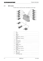
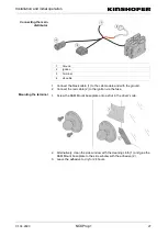
Analogue outputs
Stran
d
Function
1
Analogue Out A
2
Analogue Out B
3
GND
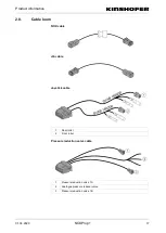
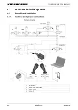
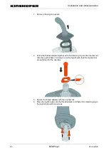
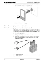
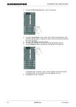
4.1.5.2. Connect the pressure reduction valve with pilot valve
If a pilot valve is installed, the pressure reduction valve is connected as follows:
1. Plug in the pressure reduction valve cable at the cab module and connect
with the pressure reduction valve.
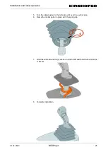
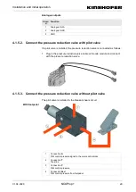
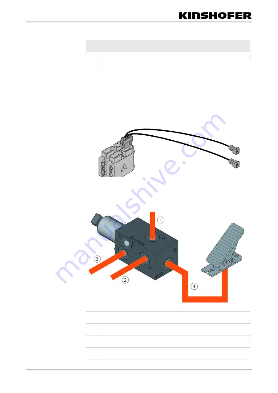
4.1.5.3. Connect the pressure reduction valve without pilot valve
The pilot valve is installed in the breaker-shears circuit.
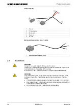
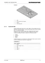
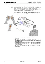
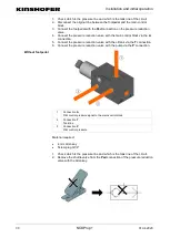
1
Connection
A
Pilot control pressure signal to the main control block
2
Connection
T
Tank line
3
Connection
P
Pilot control pressure
4
Connection
Ped
Pilot control pressure from footpedal
With footpedal


