background image

TM

Model 3700

M0275-01

Rev. 10/18 


1-3

The Kinze Limited Warranty for your new machine is stated on the retail purchaser’s copy of the Warranty And Delivery 
Receipt form. Additional copies of the Limited Warranty can be obtained through your Kinze Dealer.

Warranty, within the warranty period, is provided as part of Kinze’s support program for registered Kinze products 
which have been operated and maintained as described in this manual. Evidence of equipment abuse or modification 
beyond original factory specifications will void the warranty. Normal maintenance, service and repair is not covered by 
Kinze warranty.  

To register your Kinze product for warranty, a Warranty And Delivery Receipt form must be completed by the Kinze 
Dealer and signed by the retail purchaser, with copies to the Dealer, and to the retail purchaser. Registration must be 
completed and submitted to Kinze Manufacturing, Inc. within 5 business days of delivery of the Kinze product to the 
retail purchaser. Kinze Manufacturing, Inc. reserves the right to refuse warranty on serial numbered products which 
have not been properly registered.

If service or replacement of failed parts which are covered by the Limited  Warranty are required, it is the user’s 
responsibility to deliver the machine along with the retail purchaser’s copy of the Warranty And Delivery Receipt to 
the Kinze Dealer for service. Kinze warranty does not include cost of travel time, mileage, hauling or labor. Any prior 
arrangement made between the Dealer and the retail purchaser in which the Dealer agrees to absorb all or part of this 
expense should be considered a courtesy to the retail purchaser.

Kinze warranty does not include cost of travel time, mileage, hauling, or labor.

Warranty

Summary of Contents for 3700

Page 1: ...____________ Measured Pulses Per Mile Km Radar Distance Sensor _____________________ Measured Pulses Per Mile Km Magnetic Distance Sensor __________________ SERIAL NUMBER The serial number plate is located on the planter frame as shown below The serial number provides important information about your planter and is needed to obtain correct replacement parts Always provide model number and serial n...

Page 2: ......

Page 3: ......

Page 4: ......

Page 5: ...outed to prevent damage Inflate tires to specified air pressure and torque wheel lug bolts and lug nuts as specified in the Operator Manual All safety decals correctly located and legible Replace if damaged All reflective decals and SMV sign correctly located and visible when the planter is in transport position Safety warning lights correctly installed and working properly Paint all parts scratch...

Page 6: ...ain all operating adjustments Read warranty to retail customer end user Complete Warranty and Delivery Report form To the best of my knowledge this machine has been delivered ready for field use and customer has been fully informed as to proper care and operation Signature of Delivery Person Dealer Name Date AFTER DELIVERY CHECKLIST The following is a list of items we suggest to check during the f...

Page 7: ...Leader InCommand 1200 Display 2 35 Point Row Clutches 2 37 Two Speed Point Row Clutches 2 38 Piston Pump 2 39 Check Valves 2 40 Low Rate Pop Up Liquid Fertilizer System 2 40 Rear Trailer Hitch 24 Row 70 CM Only 2 40 Field Test 2 41 Field Check Seed Population 2 41 Determining Kilograms Per Hectare Brush Type Meter 2 42 Determining Liters Per Hectare 2 42 Field Check Granular Chemical Application 2...

Page 8: ...Adjustment 5 29 Check Valve 5 30 Dentent Lever Valve 5 30 Flow Control Valves 5 30 Pressure Relief Valves 5 30 Relief Valve Cartridge 5 30 Solenoid Valve 5 31 Stroke Limiter Valve 5 31 Chain Tension Adjustment 5 31 Stroke Limiter Height Stop Valve Adjustment 5 32 Detent Lever Lowering Control Valve Adjustment 5 33 Row Marker Bearing Lubrication or Replacement 5 34 Lift Ground Drive Wheel Bearing R...

Page 9: ...onditions Throughout this manual the symbol and the words DANGER WARNING and CAUTION are used to call attention to safety information that if not followed will or could result in death or injury NOTICE and NOTE are used to call your attention to important information The definition of each of these terms follows NOTE Special point of information or machine adjustment instructions Indicates an immi...

Page 10: ...s manual may show safety covers shields or lockup devices removed for visual clarity NEVER OPERATOR OR WORK ON machine without all safety covers shields and lockup device in place as required WARNING NOTE Some photos in this manual may have been taken of prototype machines Production machines may vary in appearance NOTE Some photos and illustrations in this manual show optional attachments install...

Page 11: ...rchaser with copies to the Dealer and to the retail purchaser Registration must be completed and submitted to Kinze Manufacturing Inc within 5 business days of delivery of the Kinze product to the retail purchaser Kinze Manufacturing Inc reserves the right to refuse warranty on serial numbered products which have not been properly registered If service or replacement of failed parts which are cove...

Page 12: ...ails Information used in this manual was current at time of printing However due to Kinze s ongoing product improvement production changes may cause your machine to appear slightly different in detail Kinze Manufacturing Inc reserves the right to change specifications or design without notice and without incurring obligation to install the same on machines previously manufactured To obtain the mos...

Page 13: ... Transport Height 11 4 3 50 m Planting Length 27 3 8 30 m Transport Length 32 2 9 80 m Planting Width 47 11 14 60 m Transport Width 13 1 4 00 m With Granular Chemical Option 14 5 4 40 m Seed Capacity 1 75 bu 62 L Hopper Vacuum 1 90 bu 67 L Hopper Mechanical Transport Tire Size 4 36 x 16 17 5 rib duplex 14 ply tubeless Wing Lift Tires 4 24R 6 36R 7 5 x 20 8 ply Tubeless Rib Implement Contact Drive ...

Page 14: ...mechanical meters 2 SCV 15 gpm 57 L min 1 SCV planter lift 2 SCV markers fold with 12v control console Base machine with vacuum meters Tractor mounted PTO hydraulic pump 2 SCV 15 gpm 57 L min 1 SCV planter lift 2 SCV markers fold with 12v control console NOTE Tractor mounted PTO hydraulic pump supplies oil flow for vacuum hydraulic circuit ...

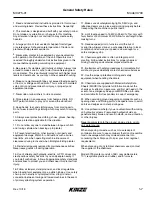
Page 15: ...all such drives follow all appropriate safety standards and practices to protect you and others near this planter from injury 16 Follow all federal state provincial and local regulations when towing farm equipment on a public highway Use safety chain not an elastic or nylon plastic tow strap to retain connection between towing and towed machines in the event of primary attaching system separation ...

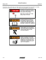
Page 16: ...nergy sources at all times DANGER Improperly operating or working on this equipment could result in death or serious injury Read and follow all instructions in Operator Manual before operating or working on this equipment WARNING Falling equipment can cause death or serious injury Install all lockup devices or lower planter to ground before working on equipment WARNING Explosive separation of rim ...

Page 17: ...how any loss of of reflective properties When replacing decals clean machine surface thoroughly with soap and water or cleaning solution to remove all dirt and grease NOTE Safety sign and decal locations are shown in the Parts Manual for this machine NOTE Style and locations of SMV sign reflective decals and safety warning lights conform to ANSI ASABE S279 14 JUL 2008 and ANSI ASABE S276 6 JAN 200...

Page 18: ...This page intentionally left blank ...

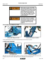
Page 19: ...r field operation Safety lockup in transport maintenance position Safety lockup in storage position ROW MARKER SAFETY LOCKUP Row marker safety lockup stored Row marker safety lockup installed Row marker can lower at any time and could cause death or serious injury Stay away from row markers Install safety lockup device when not in use WARNING Uncontrolled machine movement can crush or cause loss o...

Page 20: ...le for high speed or push in on handle for low speed operation Jack handle installed F a s t S l o w Uncontrolled movement of equipment can cause loss of control and could result in death serious injury or damage to property and equipment Install all safety pins before transporting equipment WARNING Planter hitch may raise uncontrollably during folding unfolding and can cause death serious injury ...

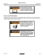
Page 21: ...is equipment could result in death or serious injury Read and follow all instructions in Operator Manual before operating or working on this equipment WARNING Explosive separation of rim and tire parts can cause death or serious injury Overinflation rim and tire servicing improper use of rims and tires or worn or improperly maintained tires could result in a tire explosion WARNING Wheel separation...

Page 22: ...port 36 x 16 x 17 5 75 PSI 517 kPa Contact drive 4 80 x 8 50 PSI 345 kPa Row marker 16 x 6 5 x 8 14 PSI 97 kPa Liquid fertilizer piston pump Not shown 4 10 x 6 50 PSI 345 kPa 3 Lubricate planter and row units per lubrication information in this manual 4 Check all drive chains for proper tension alignment and lubrication Tire locations L H mirrors R H shown Ground drive Contact drive Row marker Tra...

Page 23: ...s tillage and terrain Two dual remote hydraulic outlets SCV are required on all sizes of conventional planters equipped with row markers Four dual remote hydraulic outlets SCV are required on all sizes of bulk fill planters equipped with row markers A 12 volt DC electrical system is required on all sizes Other dual fan system components include two oil coolers two replaceable cartridge type filter...

Page 24: ...ow PTO shaft center line Make sure drawbar is in a stationary position 3 Back tractor to planter and connect with minimum 1 diameter hitch pin Make sure hitch pin is secured with a locking pin or cotter pin If tractor is not equipped with a hitch pin locking device NOTE DO NOT install safety chain using clevis mounting hardware Safety chain MUST be installed separately 4 Safety chain must be used ...

Page 25: ... leaks Relieve pressure before searching for leaks or performing any system maintenance WARNING Connect hydraulic motor case drain to a case drain return line with zero PSI on tractor Failure to connect to a return with zero PSI will cause hydraulic motor shaft seal damage DO NOT connect hydraulic motor case drain to a SCV outlet or motor return circuit connection Contact tractor manufacturer for ...

Page 26: ...ion with warning lights on tractor NOTE A 12V battery connection is required to power the vacuum fan digital gauge Connect red wire to positive battery terminal and black wire to negative battery terminal Completely raise parking jack to prevent damage to jack assembly and equipment when moving planter Color and Label Machine Function Hose Size Hose Function Red AA Field Lift Pressure Red BB Retur...

Page 27: ... injury or damage to property and equipment Properly load planter when transporting Be aware of extra transport weight and road conditions and limits WARNING Loss of control of equipment during transport can result in death serious injury or damage to property and equipment Tractor gross weight must be greater than planter gross weight with attachments and options WARNING Uncontrolled movement of ...

Page 28: ...Alloy U cup Polyester Alloy U cup Polyester Alloy U cup Polyester Alloy U cup Polyester Alloy U cup Polyester Alloy U cup Rod Wiper Polyester Alloy Snap In Polyester Alloy Snap In Polyester Alloy Snap In Polyester Alloy Snap In Polyester Alloy Snap In Polyester Alloy Snap In Polyester Alloy Snap In Polyester Alloy Snap In Piston Seal PTFE Seal PTFE Seal PTFE Seal PTFE Seal T Seal T Seal PTFE Seal ...

Page 29: ...ltural Construction Agricultural Construction Agricultural Construction Agricultural Construction Agricultural Construction Agricultural Construction Part Number A1487 A3196 A3212 A1404 A1072 A1049 Description Hose Assembly 1 2 x 150 3 8 m Hose Assembly 8 x 240 6 09 m Hose Assembly 8 x 260 6 60 m Hose Assembly x 41 1 0 m 10F 10F Hose Assembly 8 x 48 1 21 m Hose Assembly 8 x 160 4 06 m Product Cat ...

Page 30: ... Construction Agricultural Construction Agricultural Construction Agricultural Construction Agricultural Construction Agricultural Construction Part Number A1475 A1057 A1019 A1146 A1189 A12026 Description Hose Assembly 1 2 x 10⁸ 2 74 m Hose Assembly 8 x 216 5 48 m Hose Assembly 8 x 44 1 11 m Hose Assembly x 12 0 30 m Hose Assembly x 36 0 91 m Hose Assembly 8 x 148 3 76 m Product Category Hydraulic...

Page 31: ...nstruction Agricultural Construction Agricultural Construction Agricultural Construction Agricultural Construction Agricultural Construction Part Number A8500 A3140 A3111 A1026 A1031 A3161 Description Hose Assembly x 260 6 60 m Hose Assembly x 94 2 39 m Hose Assembly x 200 5 08 m 08F 08F Hose Assembly x 152 3 86 m Hose Assembly x 234 5 94 m Hose Assembly x 210 5 33 m Product Category Hydraulic Hos...

Page 32: ...ural Construction Agricultural Construction Agricultural Construction Agricultural Construction Agricultural Construction Agricultural Construction Part Number A12749 A1465 A8501 A8503 A12082 A1038 Description Hose Assembly 1 2 x 198 5 03 m Hose Assembly 1 2 x 84 2 13 m Hose Assembly 16 x 426 10 82 m Hose Assembly 16 x 436 11 07 m Hose Assembly 8 x 418 10 62 m Hose Assembly 8 x 370 9 41 m Product ...

Page 33: ... mm Minimum Bend Radius 3 89 mm 2 64 mm 2 64 mm 7 6 cm 2 64 mm 2 51 mm Working Pressure 3000 PSI 20700 kPa 3000 PSI 20700 kPa 3000 PSI 20700 kPa 3500 PSI 24100 kPa 3000 PSI 20700 kPa 3000 PSI 20700 kPa Temperature Range 40 C 100 C 40 C 100 C 40 C 100 C 40 C 100 C 40 C 100 C 40 C 100 C Material Modified Nitrile Type C2 Modified Nitrile Type C2 Modified Nitrile Type C2 Modified Nitrile Type C2 Modif...

Page 34: ... back with planter lowered to proper operating height Five holes in the hitch bracket allow clevis to be raised or lowered Clevis may be turned over for a finer adjustment between mounting holes Torque hardware to 1138 8 Nm Field and actual planting conditions determine which wheel settings to use to ensure row unit parallel arms are approximately parallel with planting surface If planting in extr...

Page 35: ...ate charts are based on standard rate drive Standard rate drive uses a 30 tooth sprocket and No 40 118 pitch chain on each contact wheel Optional half rate 2 to 1 drive is recommended only when population falls below planting rate charts Replace 30 tooth sprocket on each contact wheel with a 15 tooth sprocket and shorter No 40 110 pitch chain This reduces planter transmission speed and planting an...

Page 36: ...on idler spring Collar Wrap spring wrench L H rotation shown Chain idler tensioning SHEAR PROTECTION Determine where binding has occurred if excessive load causes a pin to shear before replacing pin Replace shear pins with same size and type Additional shear pins are in the storage area located at end of each planter wing on inboard side of transport hook Transmission shaft shear pin Spare shear p...

Page 37: ...nk slide L H shown DIGITAL VACUUM GAUGE Digital vacuum gauge control console is equipped with a power toggle switch run stop fans toggle switch and two fan speed control toggle switches for the vacuum fans Power switch applies power to control console Run stop toggle switch turns both fans on when power switch is ON Fan speed control switches adjusts each fan left or right Digital vacuum gauge con...

Page 38: ...ches are an ON OFF ON type If planter is equipped with optional Two Speed Point Row Clutch Package point row switch and reduced rate switch operate independently from rest of control console Power to marker switch is fed through auxiliary switch and two transport function switches Operating any lower row switch disables markers and turns off marker indicator light Raise wing lock and rotate tongue...

Page 39: ... without using tractor to assist may cause equipment damage especially in soft conditions or when loaded with seed or fertilizer Use tractor to reduce stress on frame drive and transport components NOTICE 3 Place tractor in reverse and hold in clutch Start unfolding planter and slowly back up tractor as planter unfolds 4 Raise planter to remove weight from center slave lift cylinder lockups and re...

Page 40: ...rallel linkage pin installed Planter hitch may raise uncontrollably during folding unfolding and can cause death serious injury or damage property and equipment DO NOT fold or unfold planter without planter attached to a tractor DO NOT unhitch planter from tractor unless fully folded for transport or fully unfolded with planting units lowered to ground WARNING DO NOT LOWER planter frame onto trans...

Page 41: ... and wings supported by wing wheels begin to unfold Place tractor transmission in a low reverse gear and slowly back up as planter unfolds Center axle tires should remain stationary and wing tires should roll in a continuous arc with minimal side loading on tires or their mounting structures Hold switch in ROTATE position until tongue cylinder is fully retracted Hitch release from wing hook Plante...

Page 42: ...ft cylinder lockups Raising planter too high will reset the mechanism If this happens lower machine until hydraulic system stalls against the automatic safety raise machine slightly to release automatic safety lock and then lower planter 5 Lower machine to ground Center drops until toolbar is level and then entire planter lowers evenly Hold tractor s hydraulic lever 5 to 10 seconds to rephase syst...

Page 43: ...frame when making field turn arounds Place hydraulic lever in float position during normal field operation Operate row markers in float position to prevent damage to row markers NOTICE Operate row markers with control console switch for that marker in ON LEFT or RIGHT position and tractor s hydraulic control After markers are lowered to ground move hydraulic control to operate markers in float pos...

Page 44: ...ive and transport components NOTICE 5 Place tractor in low forward gear and hold in clutch Start folding planter and move tractor slowly forward as planter folds to keep wing wheel side pressure to a minimum 6 Raise hitch parallel linkage to engage wing hooks 7 Install hitch parallel linkage lock pin or lockup bracket 8 Lower hitch parallel linkage cylinder NOTE Read following information for deta...

Page 45: ... safety lockup stored Row marker safety lockup installed Raising planter 2 Hold RAISE WING LOCK switch on control console in RAISE while operating proper tractor hydraulic control to raise planter Planter frame should raise level until lift master cylinders at ends of wings are fully extended Center lift slave cylinders will continue to extend at a somewhat slower rate until they are fully extende...

Page 46: ...in ROTATE and operate hydraulic control to fold planter Slowly idle tractor forward as you fold planter allowing center axle tires to remain stationary and wing tires to roll in a continuous arc with minimal side loading on tires or their mounting structure Hooks on wing ends should pass over planter hitch and contact stops on draft links Planter folding DO NOT fold planter into transport position...

Page 47: ...Install parallel linkage lock pin 8 Lower parallel link cylinder onto lock pin Wing end hook 6 Raise hitch parallel linkage to completely engage wing hooks and completely lift wing wheels off ground DO NOT LOWER planter frame onto transport axle in folded transport position or transport tires and row units will be damaged NOTICE ...

Page 48: ...er 4 Raise row marker at end of field using hydraulic control 5 After turn using the hydraulic control lower the pre selected row marker 6 Continue to follow this procedure NOTE Both row markers can be lowered by operating switch in each position and hydraulic control twice Row markers raise simultaneously with hydraulic control in raise position If electrical system does not operate properly Chec...

Page 49: ...t with tractor flow controls in maximum position After row marker speed is set adjust tractor flow controls to allow hydraulic control to stay in detent during marker raise or lower cycle NOTE Hydraulics operate slowly when oil is cold Make all adjustments with oil warm NOTE On a tractor where oil flow cannot be controlled tractor flow rate may be greater than rate marker cylinder can accept Hold ...

Page 50: ...Marker chain is PROPERLY ADJUSTED if marker blade pushes dirt 30 cm or less as marker completes fold into field operating position Chain should have some slack when marker is in field operating position Marker chain is TOO LOOSE and should be adjusted if marker blade pushes dirt more than 30 cm as it completes the fold into field operating position Marker chain is TOO TIGHT if it will not allow ma...

Page 51: ...ncave side facing inward Spindle assembly is slotted so hub and blade can be angled to throw more or less dirt 5 Loosen hardware and move assembly as required 6 Tighten bolts to specified torque 7 Do a field test to ensure markers are properly adjusted NOTE A notched marker blade is available from Kinze through your Kinze Dealer for use in more severe no till conditions Row marker disc blade angle...

Page 52: ...FAN VALVE BLOCK ASSEMBLY See Hydraulic Schematic Vacuum Fan System in Lubrication and Maintenance section NOTE Fan turns at a reduced speed If reverse pressure is applied Vacuum fan valve block Analog vacuum or pressure gauge connects directly to vacuum meter vacuum or bulk fill pressure manifold and is teed into digital sending units Only adjustment is to zero needle with no vacuum or pressure pr...

Page 53: ...ing and more are all controlled from the cab using the Integra display Four video camera inputs provide operators a better view of equipment operation and safety by allowing them to view live video on the display NOTE See Integra operator manual for installation and programming AG LEADER INTEGRA DISPLAY Ag Leader InCommand Display The InCommand 1200 is a full featured display for any precision far...

Page 54: ...This page intentionally left blank ...

Page 55: ...s over wrap spring If stop collar is allowed to rotate with input hub clutch is engaged If stop collar is stopped from rotating control tang connected to it is forced back and spring opens This allows input hub to continue rotating without transmitting torque to output hub stopping planter drive Stop collar is controlled by an electric solenoid and an actuator arm When selector switch on tractor c...

Page 56: ...ch shuts off left or right half of planter Activating reduced rate switch engages one solenoid on each clutch assembly and reduces planting rate for entire planter Point row switch must be OFF and rate switch left in FULL RATE when planter is not in use or tractor battery will be drained NOTICE NOTE Liquid fertilizer piston pump has its own drive wheel and is not affected by point row clutch Two s...

Page 57: ... with pump and flow divider with this manual CLEANING Clean tanks hoses and metering pump thoroughly with water at end of planting season or prior to an extended period of non use Do not allow fertilizer to crystallize from cold temperature or evaporation On machines equipped with piston pump take apart and clean strainer located between piston pump and ball valve daily Remove the end cap to clean...

Page 58: ...ing the set screws at rear of outer tube removing 1 x 8 bolt at center of hitch and sliding hitch in or out to one of 4 sets of adjustment holes Reinstall and tighten hardware Hitch position during lift Optional low rate check valves are available for in line installation between liquid fertilizer piston pump and openers to ensure equal distribution of product at low rates Check valves eliminate a...

Page 59: ...n all rows See Field Check Granular Chemical Application Check for desired depth placement and seed population on all rows See Field Check Seed Population Check for proper application rates of fertilizer on all rows See Fertilizer Application Rate Chart Reinspect machine after field testing Hoses And Fittings Bolts And Nuts Cotter Pins And Spring Pins Drive Chain Alignment 1 Tie up one or more set...

Page 60: ...d a finger has lost its seed and not functioned properly If two seeds are found within a short distance of each other finger has metered two seeds instead of one 3 See Seed Meter Finger Pickup Troubleshooting or Seed Meter Brush Type Troubleshooting in Troubleshooting Section of this manual 1 1000 Acre Seed Population Count Row Width Distance Row Width 70 cm Distance 14 28 m DETERMINING KILOGRAMS ...

Page 61: ...ll rows METERING GATE Use metering gate setting as a starting point for distributing insecticide or herbicide Charts are based on 8 km h planting speed Use a higher gate setting for speeds faster than 8 km h and a lower setting for speeds slower than 8 km h FIELD CHECK GRANULAR CHEMICAL APPLICATION Temperature humidity speed ground conditions flowability of different material or meter obstructions...

Page 62: ...at the end of each planting season Drain tank if environmental conditions are 0 Celsius or below to prevent tank from cracking NOTICE The water tank is to be used in the event of an accidental exposure to chemical Chemicals are supplied with Material Safety Data Sheets MSDS that provide full information about the chemical its effects on exposure and first aid needs in the event of an emergency Kee...

Page 63: ... at average depth approximately 5 cm while heavy soil requires increased down force Eccentric bushings in the wheel arm stop allow for lateral adjustment of the V closing wheel assembly Use a wrench to loosen hardware attaching closing wheel arm to wheel arm stop Use another wrench to turn eccentric bushings until closing wheels are aligned with seed trench Tighten hardware Closing wheels can be i...

Page 64: ... arm tab and locking nut Loosen locking nut and turn adjusting bolt in to increase down force or out to decrease down force Tighten locking nut against spring plug Adjust all row units to a similar setting COVERING DISCS SINGLE PRESS WHEEL ADJUSTMENT Drag closing attachment pulls loose soil over seed trench NOTE Use of a seed firming wheel or other seed firming device is recommended with drag clos...

Page 65: ...shing fields Turn knob turn counterclockwise to release or turn clockwise to engage drive SEED METER DRIVE RELEASE Seed meter drive release Mechanical seed hopper has a capacity of 67 L Vacuum seed hopper has a capacity of 62 L Use clean seed and make certain there are no foreign objects inside when filling seed hopper Replace hopper lids after hoppers are filled to prevent accumulation of dust or...

Page 66: ...spect and replace weak worn or broken springs idlers and idler bushings ROW UNIT CHAIN ROUTING Row unit granular chemical drive Mechanical pull row unit meter drive NOTE Reverse idler when worn on one side for extended use NOTE Install connector link with closed end facing direction of travel Closed end Direction of travel Vacuum pull row unit meter drive ...

Page 67: ...t top of spring 2 Slide mount to desired position and install pin NOTE Adjust springs for field conditions Too much down pressure in hard field conditions can cause row units to lift planter and keep drive wheels from making contact Too much down pressure in soft field conditions can cause row unit to run too deep There are four positions to set down pressure spring tension Four springs per row Qu...

Page 68: ...l row unit air spring Pull row unit assist springs Packages include upper and lower air spring mounting castings for pull row units 150 PSI 1034 kPa rated air springs O D nylon hoses dual solenoid air valve and stainless steel 160 PSI 1103 kPa 2 liquid filled gauge and planter wiring harness Pneumatic down pressure row unit extension brackets are required in some applications NOTE Assist springs a...

Page 69: ...essor assembly Control console ADJUST DOWN PRESSURE FROM CAB Push toggle switch left to increase or right to decrease pressure ADJUST DOWN PRESSURE AT PLANTER Push and hold decrease or increase button on compressor assembly to decrease or increase pressure NOTE Value on the air pressure gauge is NOT down pressure force Multiply air pressure PSI by four 4 to calculate down pressure Air compressor a...

Page 70: ... Talc High Rate Large Milo Grain Sorghum Yellow GA6633 GD8237 60 22 000 to 30 800 seeds kg Talc Cotton Acid Delinted White GA5796 GD11122 30 9 240 to 11 440 seeds kg Talc Large Cotton Acid Delinted Tan GA6168 GD11122 36 8 360 to 9 680 seeds kg Talc High Rate Cotton Acid Delinted Light Green GA6478 GD11122 48 9 240 to 11 440 seeds kg Talc Hill Drop Cotton Acid Delinted Brown GA6182 GD11122 12 3 to ...

Page 71: ... seed meter which will cause premature wear NOTICE NOTE Clean seed is required to ensure accurate seed metering from brush type seed meters Remove seed discs daily and check seed meter or brushes for buildup of foreign material such as hulls stems etc Shown without seed disc installed FINGER PICKUP SEED METER Crop Fingers Lubricant Corn Part No GR1848 Finger Assembly Corn Graphite Talc No 1 and or...

Page 72: ... Sunflower G9042X B0684 Gray 1 row 5 punches Gray 40 Oil seeds 5 2 5 8 13 20 Graphite Talc Bayer Fluency if mandated Specialty Disc 1 G9272X B0912 Green 1 row 6 punches Green 60 Cotton 2 15 20 37 50 Graphite Talc as needed Bayer Fluency if mandated Specialty Disc 2 G9273X B0914 Brown 1 row 6 punches Green 60 Black turtle navy edible beans 2 15 20 38 51 Graphite Talc as needed Bayer Fluency if mand...

Page 73: ...ght weight seed can affect meter performance Use 118 ml of talc with each standard hopper fill of seed and mix thoroughly to coat all seeds and adjust rates as needed Use of talc aids seed flow into meter singulation and disc seed drop NOTE Foreign material in seed disc orifices such as seed chips hulls stems etc may affect seed delivery Clean seed ensures accurate seed metering from vacuum seed m...

Page 74: ...al setting Seed size seed shape seed treatments travel speed and planting rate all affect meter performance 3 With vacuum fan running lower planter to planting position and drive forward a short distance to load seed into seed disc cells 4 Adjust vacuum level to initial setting according to tables on page NOTE Vacuum reading will be much lower when seed disc cells are empty Load all seed cells bef...

Page 75: ...y hopper on its right side Push release button and rotate seed meter vacuum cover clockwise to align keyhole slots with bolt heads Lift off cover 4 Rotate seed disc hub clockwise to unlock and remove seed disc 5 Empty meter 6 Thoroughly inspect meter to ensure all seed is removed 7 Replace seed disc Install vacuum cover 4 Adjust vacuum level to initial setting according to tables on page NOTE Vacu...

Page 76: ...o retard buildup of seed treatments on meter components More frequent cleaning of monitor seed tubes may be necessary due to use of additional graphite Talc seed lubricant may be used as a drying agent in addition to graphite lubrication The drying agent may improve seed release and or to retard buildup of seed treatments on meter components 1 Fill hopper full of seed add 60 ml cup conventional of...

Page 77: ...ing wear life characteristics of meters and bulk fill systems that use Bayer Fluency Agent are not yet known Please follow Bayer Fluency Agent instructions for rates and mixing directions NOTE Presently Bayer Fluency Agent is only required to be used in Canada with Bulk Fill or Vacuum planters that plant corn or beans treated with neonicotinoids Farms outside of Canada farms not using seed treated...

Page 78: ...rings to specification shown in following table Frame Mounted Coulter Spring Downpressure Settings End flush with spring anchor bar Extended 1 cm through spring anchor bar All threads used 125 kg 181 kg 227 kg Frame mounted coulter adjustment Spring adjustment bolt Spring anchor bar Blade depth adjustment holes RESIDUE WHEELS FRAME MOUNTED COULTER Residue wheels attach to frame mounted coulter wit...

Page 79: ...r pushing ROW UNIT MOUNTED DISC FURROWER PULL ROW Vertical adjustment can be made in 8 mm increments Remove lynch pin in vertical support arm and move arm up or down Reinstall lynch pin Finer adjustment can be made by removing lynch pin and using x 2 set screw to clamp support arm in position Slotted holes in support arm allow front to rear disc blade adjustment Blades can be adjusted so front edg...

Page 80: ...jam nut located on the upper link sets maximum depth for loose soil conditions Initial setting is 1 45 mm above row unit double disc opener depth Three holes in upper link adjust wheel angle With wheel mount in most vertical position using the rear hole in the upper link the residue wheel is most aggressive Moving wheel mount to a forward hole reduces aggressiveness of residue wheel for use in mul...

Page 81: ...can be used on pull row units and push row units Align spiked closing wheels straight across from each other in most rearward holes on closing wheel arm Set the wheels 1 1 25 31 mm apart at the closest point If large amounts of contouring is being done mount wheels in the forward most hole This will reduce drifting of row unit Row Unit Spiked Closing Wheel ...

Page 82: ...ulter mounted residue wheels Coulter mounted residue wheels Residue wheels attach to row unit mounted coulter with two cap screws and sleeves allowing unit to free float A 2 position spindle bolt mounting positions wheels interlocked or staggered Depth adjustment is made with a spring loaded cam and pin with 11 positions in 6 mm increments A high point on the cam allows wheels to be locked up A we...

Page 83: ...ckwise to disengage and turn clockwise to engage Slotted holes in hopper support panel and clutch housing allow for alignment adjustment between clutch drive coupler and meter shaft Granular chemical hopper Granular chemical drive release Spring tooth incorporator smooths soil behind row unit and incorporates granular chemicals Adjust two mounting chains on each spring tooth incorporator so there ...

Page 84: ...e compensating banding straight drop in furrow placement or 14 355 mm rear banding NOTE Granular chemical rear bander is not compatible with covering discs single press wheel option Optional granular chemical bander shield is installed on underside of wheel arm stop to shield crop residue from lodging in granular chemical bander GRANULAR CHEMICAL BANDER SHIELD 16 x 1 hex head cap screw Wheel arm s...

Page 85: ...an Milo Grain Sorghum Acid Delinted Cotton Rate charts are given in seeds per acre as well as seed spacing in inches rounded to nearest tenth of an inch Because of large range in seed size pounds per acre is not a suggested method of selecting transmission settings Smaller size seed pounds per acre may be below what was expected and large seed pounds per acre may appear above expectations To deter...

Page 86: ...0 8 6 to 10 25 26 68951 20 7 6 to 10 26 27 69053 20 7 6 to 10 27 28 69150 20 7 6 to 10 23 23 71711 19 9 6 to 10 28 27 74365 19 2 6 to 10 27 26 74468 19 2 6 to 10 25 24 74699 19 1 6 to 10 24 23 74828 19 1 6 to 10 28 26 77225 18 5 6 to 10 27 25 77445 18 4 6 to 10 25 23 77946 18 3 6 to 10 19 17 80146 17 8 6 to 10 28 25 80316 17 8 6 to 10 27 24 80673 17 7 6 to 10 26 23 81063 17 6 6 to 10 28 24 83662 1...

Page 87: ...7 5 1 3 to 13 26 27 345270 4 1 276217 5 1 3 to 13 23 23 358550 4 1 286839 5 1 3 to 13 27 26 372338 3 8 297871 4 8 3 to 13 24 23 374138 3 8 299310 4 8 3 to 13 25 23 389726 3 6 311780 4 6 3 to 13 19 17 400731 3 6 320584 4 6 3 to 13 27 24 403367 3 6 322693 4 3 3 to 13 28 24 418307 3 3 334645 4 3 3 to 13 23 19 434032 3 3 347225 4 1 3 to 13 28 23 436493 3 3 349194 4 1 3 to 13 24 19 452904 3 0 362321 4 ...

Page 88: ...04 8 3 26 27 207161 6 9 172634 8 3 23 23 215129 6 6 179275 8 0 27 26 223403 6 4 186169 7 7 24 23 224482 6 4 187068 7 6 25 23 233835 6 1 194863 7 3 19 17 240438 5 9 200367 7 1 27 24 242020 5 9 201685 7 1 28 24 250983 5 7 209155 6 8 23 19 260419 5 5 217017 6 6 28 23 261896 5 5 218247 6 5 24 19 271744 5 3 226451 6 3 25 19 283065 5 0 235887 6 1 23 17 291138 4 9 242547 5 9 26 19 294387 4 9 245323 5 8 2...

Page 89: ...Speed Range km h 70 cm Rows 17 28 43538 32 8 3 to 13 17 27 45151 31 6 3 to 13 17 26 46887 30 5 3 to 13 19 28 48660 29 4 3 to 13 19 27 50462 28 3 3 to 13 17 24 50795 28 1 3 to 13 17 23 53003 27 0 3 to 13 19 25 54500 26 2 3 to 13 19 24 56770 25 2 3 to 13 23 28 58905 24 3 3 to 13 19 23 59238 24 1 3 to 13 24 28 61466 23 2 3 to 13 24 27 63742 22 4 3 to 13 17 19 64162 22 3 3 to 13 24 26 66194 21 6 3 to ...

Page 90: ...21 3 67321 19 23 6 to 10 21 2 69419 23 27 6 to 10 20 6 69852 24 28 6 to 10 20 5 71904 15 17 6 to 10 19 9 72437 24 27 6 to 10 19 7 72916 17 19 6 to 10 19 6 74973 23 25 6 to 10 19 1 75673 26 28 6 to 10 18 9 78096 23 24 6 to 10 18 3 78234 24 25 6 to 10 18 3 78583 27 28 6 to 10 18 2 81494 23 23 6 to 10 17 5 84512 28 27 6 to 10 16 9 84628 27 26 6 to 10 16 9 85036 24 23 6 to 10 16 8 87761 28 26 6 to 10 ...

Page 91: ...16 23 27 6 to 10 14 0 102448 24 28 6 to 10 13 9 105461 15 17 6 to 10 13 5 106241 24 27 6 to 10 13 4 106943 17 19 6 to 10 13 4 109961 23 25 6 to 10 13 0 110983 26 28 6 to 10 12 9 114545 23 24 6 to 10 12 5 114741 24 25 6 to 10 12 5 115255 27 28 6 to 10 12 4 119524 23 23 6 to 10 12 0 123949 28 27 6 to 10 11 5 124121 27 26 6 to 10 11 5 124718 24 23 6 to 10 11 5 128715 28 26 6 to 10 11 1 129086 27 25 6...

Page 92: ... 10 10 2 141256 26 28 6 to 10 10 1 145783 23 24 6 to 10 9 8 146036 24 25 6 to 10 9 8 146687 27 28 6 to 10 9 7 152120 23 23 6 to 10 9 4 157753 28 27 6 to 10 9 1 157971 27 26 6 to 10 9 0 158732 24 23 6 to 10 9 0 163824 28 26 6 to 10 8 7 164289 27 25 6 to 10 8 7 165349 25 23 6 to 10 8 6 170016 19 17 6 to 10 8 4 171135 27 24 6 to 10 8 3 171961 26 23 6 to 10 8 3 177473 28 24 6 to 10 8 0 178576 27 23 6 ...

Page 93: ...4 6 to 10 12 2 117350 24 25 6 to 10 12 2 117872 27 28 6 to 10 12 1 122238 23 23 6 to 10 11 7 126768 28 27 6 to 10 11 3 126940 27 26 6 to 10 11 3 127553 24 23 6 to 10 11 2 131642 28 26 6 to 10 10 9 132019 27 25 6 to 10 10 8 132869 25 23 6 to 10 10 8 136621 19 17 6 to 10 10 5 137519 27 24 6 to 10 10 4 138184 26 23 6 to 10 10 3 142611 28 24 6 to 10 10 0 143499 27 23 6 to 10 10 0 147975 23 19 6 to 10 ...

Page 94: ...8 7 166479 26 28 6 to 10 8 6 171813 23 24 6 to 10 8 3 172114 24 25 6 to 10 8 3 172881 27 28 6 to 10 8 3 179286 23 23 6 to 10 8 0 185924 28 27 6 to 10 7 7 186180 27 26 6 to 10 7 7 187078 24 23 6 to 10 7 6 193077 28 26 6 to 10 7 4 193628 27 25 6 to 10 7 4 194874 25 23 6 to 10 7 3 200377 19 17 6 to 10 7 1 201695 27 24 6 to 10 7 1 202669 26 23 6 to 10 7 0 209165 28 24 6 to 10 6 8 210465 27 23 6 to 10 ...

Page 95: ...11882 26 28 6 to 10 6 7 218672 23 24 6 to 10 6 5 219054 24 25 6 to 10 6 5 220030 27 28 6 to 10 6 5 228180 23 23 6 to 10 6 3 236632 28 27 6 to 10 6 0 236958 27 26 6 to 10 6 0 238101 24 23 6 to 10 6 0 245732 28 26 6 to 10 5 8 246434 27 25 6 to 10 5 8 248021 25 23 6 to 10 5 8 255026 19 17 6 to 10 5 6 256702 27 24 6 to 10 5 6 257942 26 23 6 to 10 5 5 266210 28 24 6 to 10 5 4 267865 27 23 6 to 10 5 3 2...

Page 96: ...34 26 28 6 to 10 4 3 343605 23 24 6 to 10 4 2 344202 24 25 6 to 10 4 2 345741 27 28 6 to 10 4 1 358545 23 23 6 to 10 4 0 371825 28 27 6 to 10 3 8 372336 27 26 6 to 10 3 8 374133 24 23 6 to 10 3 8 386124 28 26 6 to 10 3 7 387227 27 25 6 to 10 3 7 389723 25 23 6 to 10 3 7 400725 19 17 6 to 10 3 6 403364 27 24 6 to 10 3 5 405312 26 23 6 to 10 3 5 418301 28 24 6 to 10 3 4 420900 27 23 6 to 10 3 4 4340...

Page 97: ...6 28 6 to 10 4 3 343629 23 24 6 to 10 4 2 344226 24 25 6 to 10 4 2 345762 27 28 6 to 10 4 1 358569 23 23 6 to 10 4 0 371849 28 27 6 to 10 3 8 372360 27 26 6 to 10 3 8 374160 24 23 6 to 10 3 8 386151 28 26 6 to 10 3 7 387254 27 25 6 to 10 3 7 389748 25 23 6 to 10 3 7 400755 19 17 6 to 10 3 6 403391 27 24 6 to 10 3 5 405338 26 23 6 to 10 3 5 418331 28 24 6 to 10 3 4 420929 27 23 6 to 10 3 4 434056 2...

Page 98: ...7 19 6 to 10 3 5 419851 23 25 6 to 10 3 4 423764 26 28 6 to 10 3 4 437346 23 24 6 to 10 3 3 438107 24 25 6 to 10 3 3 440063 27 28 6 to 10 3 2 456361 23 23 6 to 10 3 1 473262 28 27 6 to 10 3 0 473913 27 26 6 to 10 3 0 476202 24 23 6 to 10 3 0 491464 28 26 6 to 10 2 9 492868 27 25 6 to 10 2 9 496045 25 23 6 to 10 2 9 510049 19 17 6 to 10 2 8 513406 27 24 6 to 10 2 8 515886 26 23 6 to 10 2 8 532421 2...

Page 99: ...rd for 53m 3 Measure fluid mL caught in container and divide that amount by 4 Result is liters fertilizer delivered per hectare when planting in 70 cm rows e g 20ml 2 L 50ml 5L 100ml 10L 4 Rinse collection container and repeat test on other rows if necessary Model NGP 7055 Pumps With 18 Tooth Sprocket and Ground Drive Planter equipped with two piston pumps Pump Setting 2 3 4 5 6 7 8 9 10 24 Row 70...

Page 100: ... 45 0 DRY INSECTICIDE APPLICATION RATES APPROXIMATE KG HECTARE AT 8 km h NOTE Chart represents average values and should be used only as a starting point Granular chemical flows through meter opening at a nearly uniform rate regardless of roller speed Your actual rate will vary depending on insecticide planting speed and plant population Planting speed ground speed has the greatest effect on appli...

Page 101: ...ts average values and should be used only as a starting point Granular chemical flows through given meter opening at a nearly uniform rate regardless of roller speed Your actual rate will vary depending on specific herbicide planting speed and plant population Planting speed ground speed has the greatest effect on application rate Field check your actual rate with herbicide you are using at speed ...

Page 102: ...This page intentionally left blank ...

Page 103: ...ricated for life and are not serviceable Lubricate at frequency indicated with SAE multipurpose grease Lubricate at frequency indicated with high quality SAE 10 weight oil or spray lubricant SEALED BEARINGS Sealed bearing Typical WHEEL BEARINGS All drive transport and marker hub wheel bearings should be repacked annually and checked for wear 1 Raise wheel off ground 2 Check for bearing endplay by ...

Page 104: ...ng conditions such as dirt temperature or speed may require more frequent lubrication If a chain becomes stiff it should be removed soaked and washed in solvent to loosen and remove dirt from joints Soak chain in oil so lubricant can penetrate between rollers and bushings Row unit granular chemical drive chains Row unit drive chains Transmission chains Contact wheel drive chains ...

Page 105: ...TM Model 3700 M0275 01 Rev 10 18 5 3 Lubrication and Maintenance Inner module point row clutch drive chains Optional piston pump drive chain Row Unit Electric Clutches ...

Page 106: ...shers with proper part Torque hardware to 176 Nm Row unit parallel linkages 8 per row Row unit v closing wheel covering discs single press wheel and or drag closing wheel eccentric bushings 2 per row Row unit mounted disc furrower parallel linkages 6 per row Contact wheel arm 2 per assembly SLIDING HITCH LINKAGE Inspect linkage daily to ensure free movement of axle links in slides Keep axle link s...

Page 107: ...level check plug Fill as needed with EP 90 weight gear oil Total oil capacity is approximately pint Refer to operator and instruction manual supplied with pump and flow divider for more information Piston pump oil fill and check plug locations Fill plug Check plug PTO SHAFT COUPLING PTO pump installed WRAP SPRING WRENCH ASSEMBLY Wrap spring wrench components may require occasional lubrication to o...

Page 108: ...nditions Severe or unusual conditions may require more frequent attention NOTE Numbers on illustration above correspond to photos on following pages showing lubrication frequencies 2 Ground drive wheel pivot 2 per wheel module 1 Axle and automatic safety lock pivots 7 Bulk fill Only Uncontrolled machine movement can crush or cause loss of control resulting in death serious injury or damage to prop...

Page 109: ...de General locations shown 6 Wing pivot knuckle 3 per knuckle on horizontal shaft 5 Seed rate transmission assembly idler pivot 1 per assembly 3 Upper and lower hitch linkage 2 per link 8 Axle link assemblies 1 per assembly Rear wear pads 2 sets 16 7 Link assemblies 1 per assembly Front wear pads 4 ...

Page 110: ...vot knuckle 1 per knuckle on shaft Helper cylinders 1 per cylinder 11 Transport wheel bearing 1 per wheel hub 9 Wheel module lift cylinder mount 1 per wheel module Annually 12 Swivel block 1 Annually 13 Rear trailer hitch pivot 2 14 36 Row bulk fill catwalk extension pivots 2 ...

Page 111: ...H side 1 Fill until grease seeps out of bottom drain hole Piston pump R H side 3 Notched single disc opener 1 per arm Gauge wheel arms 2 Seals in gauge wheel arm are installed with lip facing out to allow grease to purge dirt away from seal Pump grease into arm until fresh grease appears between washers and arm ...

Page 112: ... planter for the first time and periodically thereafter WARNING Over tightening hardware can reduce its shock load capacity and cause equipment failure NOTICE TORQUE VALUES CHART PLATED HARDWARE Grade 2 No marks Grade 5 3 marks Grade 8 6 marks Diameter Coarse Fine Coarse Fine Coarse Fine 5 6 Nm 6 3 Nm 8 6 Nm 9 8 Nm 12 Nm 14 Nm 5 16 11 Nm 12 Nm 18 Nm 19 Nm 24 Nm 27 Nm 20 Nm 23 Nm 31 Nm 35 Nm 45 Nm ...

Page 113: ...T Non Nylock Nut Nylock Nut 20 55 70 ft lb 75 95 Nm 45 55 ft lb 61 75 Nm 16 115 125 ft lb 156 169 Nm 100 115 ft lb 136 156 Nm 14 150 180 ft lb 203 244 Nm 130 150 ft lb 176 203 Nm 1 14 275 330 ft lb 373 447 Nm 250 275 ft lb 339 373 Nm 1 12 300 375 ft lb 407 508 Nm 275 300 ft lb 373 407 Nm 1 12 300 375 ft lb 407 508 Nm 275 300 ft lb 373 407 Nm Maintain proper tire pressure Inflating a tire above or ...

Page 114: ...17 kPa Transport 36 x 16 x 17 5 75 PSI 517 kPa Contact drive 4 80 x 8 50 PSI 345 kPa Row marker 16 x 6 5 x 8 14 PSI 97 kPa Liquid fertilizer piston pump Not shown 4 10 x 6 50 PSI 345 kPa Tire locations L H mirrors R H shown Ground drive Contact drive Row marker Transport Over inflation of tires can result in explosive separation of rim and tire and cause death or serious injury Different size rims...

Page 115: ...ove cotter pin cover nut and adjusting nut and wave washer If applicable from drive shaft 2 Carefully lift finger holder with fingers and cam off shaft and clean 3 Check brush for wear and replace if necessary or after every 41 hectares per row of operation Approximately 984 hectares of corn or sunflowers on a 24 row machine NOTE It is not necessary to remove finger holder to replace brush 4 Remov...

Page 116: ... as shown above If belt is replaced A diagram molded into drive sprocket shows correct orientation Indentations CLEANING FINGER PICKUP SEED METER FOR STORAGE 1 Disassemble meter and blow out any foreign material 2 Wash ONLY in mild soap and water Do not use gasoline kerosene or any other petroleum based product Dry thoroughly 3 Coat lightly with a rust inhibiter 4 Rotate finger assembly so finger ...

Page 117: ... area between seed loading slots Wear affects planting accuracy at high RPM Lay a straight edge across disc surface at agitation groove area and measure gap between disc and straight edge If agitation groove areas are worn in excess of 0 76 mm and accuracy starts to drop off at higher meter RPM replace seed disc Estimated seed disc life expectancy under normal operating conditions is approximately...

Page 118: ... in seed disc pocket as disc rotates through seed retention area to prevent seed from dropping out of disc pocket A damaged spot excessive brush wear or foreign material lodged in brush may greatly reduce meter performance Replace upper brush at 50 160 hectares per row of use or sooner if damage or excessive wear is found Position upper brush into inner perimeter of seed retention area Make sure b...

Page 119: ...This page intentionally left blank ...

Page 120: ...gh vacuum is required or if consistent operation cannot be achieved See Preparation for Storage on page 5 38 for additional Vacuum Seed Metering System maintenance NOTE Remove seed discs from meters for annual storage and store them vertically on a dowel or pipe Vacuum Front Cover VACUUM SEED METER MAINTENANCE Singulator Seed Meter with Back Cover Removed SEED METER CLEANOUT NOTE Use of damaged se...

Page 121: ...esirable to space gauge wheel further from blade when operating in sticky soils Shim gauge wheel to lightly contact opener disc blade Check adjustment in field position GAUGE WHEEL ADJUSTMENT Gauge wheel adjustment Machine bushings 1 Remove gauge wheel and arm assemblies from shank assembly 2 Remove x cap screw that locks pivot spindle in place and remove spindle 3 Install replacement spindle and ...

Page 122: ...al with grease 6 Drive press seal into place with lip to outside NOTE Use extra care to protect the sealing lip during installation Apply uniform pressure to assemble the seal into the bore of the arm Never apply a direct hammer blow to the seal surface 7 Inspect gauge wheel pivot spindle 8 Reinstall gauge wheel arm assembly and gauge wheel NOTE Use special machine bushing between gauge wheel arm ...

Page 123: ...ns against each other there should be only light resistance to turning Re adjust blade scraper if necessary to center it between the blades NOTE Replace blades If proper blade to blade contact cannot be maintained after relocating machine bushings or if blade diameter wears below 37 cm 15 SEED OPENER DISC BLADE BEARING ASSEMBLY Approximately 25 mm 13 mm blade to blade contact Excessive blade conta...

Page 124: ...s only with disc blades of equal thickness 4 Install bearing dust cap scraper and gauge wheel REPLACE BEARING ONLY 1 Remove gauge wheel scraper bearing cap cap screw washer and disc blade bearing assembly 2 Remove rivets from bearing housing to expose bearing 3 Installing new bearing install three evenly spaced cap screws into three of six holes in bearing housing to hold bearing and bearing housi...

Page 125: ...o till planting or planting in hard ground conditions especially when planter is not equipped with no till coulters and or excessive blade to blade contact increases seed tube guard wear and requires more frequent inspection and or replacement FRAME MOUNTED COULTER NOTE Torque spindle hardware to 163 Nm See Frame Mounted Coulter in Row Unit Operation section of this manual for depth and spring adj...

Page 126: ...racket at frequency indicated in Lubrication of this section Check each bolt for proper torque If bolt is loose it should be removed and bushing inspected for cracks and wear Replace bushings as necessary NOTE Use only hardened flat washers Replace damaged flat washers with proper part Torque bolts to 176 Nm Blade hubs are equipped with sealed bearings Replace bearings if a bearing sounds or feels...

Page 127: ...ck nuts and hardware periodically for proper torque Be sure coulter is positioned square with row unit and aligned in front of row unit disc opener NOTE Torque spindle hardware to 162 Nm Coulter blade can be adjusted to one of four settings Initially blade is set in highest position As blade wears it can be adjusted to one of three lower settings See Row Unit Mounted No Till Coulter in Row Unit Op...

Page 128: ...ken parts Check for loose hardware and tighten as needed Spring tooth incorporator 1 Remove 20 x cap screw securing idler with sprockets to wrench tightener shaft and remove wrap spring wrench from planter 2 Remove split rings and disassemble as shown above Soak metal parts in solvent and thoroughly clean NOTE L H and R H release collars and torsion springs are different Order correct parts for ea...

Page 129: ...c maintenance Two speed point row clutch is similar in design and operation to standard point row clutch except for two speed function Solenoid Single point row clutch main parts Two speed point row clutch main parts Input hub Output hub Wrap spring Stop collar Actuator arm Plunger Spring Stop collar Actuator arm Plunger Input hub Output hub Wrap spring Solenoid Spring Wrap spring Stop collar ...

Page 130: ...r with a metal object to check if it is electrically magnetized Check clutch and wiring harness for power with a test light or volt meter NOTE R H clutch operates clockwise and L H clutch operates counterclockwise Clutch parts such as the wrap spring are side specific Use correct repair part if a clutch must be repaired Also see Point Row Clutch Troubleshooting in Troubleshooting section NOTE Repl...

Page 131: ...t manifold system and it may be necessary to adjust digital readout to match actual vacuum at meter Load seed discs with seed and compare digital vacuum gauge readouts to reading taken from analog gauges or a hand held gauge at several meters along length of planter Elbow connections located on covers of seed meters allow testing of meter vacuum levels without removing vacuum hoses Oil cooler loca...

Page 132: ...ise and lower speed as part of assembly procedure or upon initial operation If valve fails to function properly or requires frequent adjustment it should be removed for inspection Check for foreign material and contamination on valve and seating areas of valve body Replace defective components DENTENT LEVER VALVE Detent lever valve located near tower assembly on R H side of machine blocks oil flow...

Page 133: ...zed and no click will be heard Coil Cartridge STROKE LIMITER VALVE Stroke limiter valve located near tower assembly on L H side of machine limits height planter will raise during turn around when planter is in field operation Contact your Kinze Dealer for service CHAIN TENSION ADJUSTMENT Most drive chains have a spring loaded idler and are self adjusting The only adjustment needed is to shorten ch...

Page 134: ...g valve plunger aligned with pivot shaft Slide stroke limiter valve up or down in slotted mounting holes as needed to adjust Tighten stroke limiter valve mounting bolts and recheck adjustment Be sure detent arm is positioned as shown and tighten detent arm clamping bolt 5 Raise planter until stroke limiter valve height stop assembly halts lift cylinder Toolbar should measure 99 cm 104 cm from grou...

Page 135: ...m to depress plunger on detent lever valve allowing wing cylinders to start retracting 3 Lower planter If center of planter drops lower than wings loosen set screws and rotate cam clockwise If wing cylinder begins to retract too early and wings drop lower than center of planter rotate cam counterclockwise Adjust cam with planter in raised position 4 After final adjustment remove one set screw and ...

Page 136: ...ill the space between the bearing cups in the hub with grease 8 Install rubber seal into grease seal Place inner bearing in place and press in new rubber seal grease seal 9 Clean spindle and install hub 10 Install outer bearing washer and slotted hex nut Tighten slotted hex nut while rotating hub until there is some drag This ensures all bearing surfaces are in contact Back off slotted nut to near...

Page 137: ...ub with grease 6 Place inner bearing in place 7 Clean spindle and install hub 8 Install outer bearing and jam nut Tighten jam nut while rotating hub until there is some drag This ensures all bearing surfaces are in contact Back off jam nut turn or until there is only slight drag when rotating hub Install second jam nut to lock against first 9 Install wheel on hub Tighten hardware evenly LIFT GROUN...

Page 138: ...owards bearing 9 Clean axle spindle and install hub 10 Install outer bearing 2 washer and slotted nut Tighten slotted nut while rotating hub until there is some drag This ensures all bearing surfaces are in contact Back off slotted nut to nearest locking slot and install cotter pin Check bearing endplay 11 Fill dust cap half full of wheel bearing grease and install on hub with four hex head cap sc...

Page 139: ...water for 30 to 60 seconds then drain water before storage FERTILIZER CHECK VALVE CLEANING AND REPAIR 1 Unscrew valve body and separate halves Note direction and location of parts 2 Clean and inspect parts Flush with clean water Replace damaged parts 3 Reassemble exactly as shown O ring and valve seat must be firmly in place inside each half of valve body Direction of flow Valve seat Valve ball Gu...

Page 140: ...tings of dust and debris Clean breather on analog vacuum and pressure gauges Disassemble clean and grease all U joint slides Grease or paint disc openers blades and row marker disc blades to prevent rust Flush liquid fertilizer tanks hoses and metering pump with clean water See Piston Pump Storage if applicable Empty dry fertilizer hoppers Clean hoppers Disassemble and clean metering augers Reasse...

Page 141: ... Model 3700 Front Folding Planters meet ASABE Standards Check with tractor manufacturer for correct wiring harness to be wired into lights on your tractor Optional customer supplied auxiliary lights and wires may be wired into existing plug terminals ELECTRICAL WIRING DIAGRAM FOR LIGHT PACKAGE ...

Page 142: ...KERS WILL NOT FUNCTION WITH AUXILIARY SWITCH ON RIGHT fi Pin C Black Red Ground Pin T Black Ground Black 12 VDC Red 12 VDC Pin B Blue Red Rotate Pin W Orange Black Auxiliary Pin R Brown Left point row clutch Pin G Orange Right point row clutch Pin H Blue Left marker Pin O Red Right marker Main fuse 15A Delay Action Fuse 10A Slow Blow Point row clutch switch Auxiliary switch Rotate Tongue switch In...

Page 143: ...range Black Q T U V S R P O N M Red Black Blue Black Yellow Black Brown Black Red Orange Red F K J G H E D B C A Yellow Red Orange Blue White Black Red Blue Red Wire Color Monitor A Data 14 Auxiliary 14 Raise to Transport Reduced Rate Right Marker Right Monitor A Ground Point Row Left Reduced Rate Left Ground 12 12 14 12 12 14 14 Wire Ga Monitor A 12V Point Row Right Marker Left Wing Lock Tongue R...

Page 144: ...lack Red Orange Red Blue Red Green White Black Wire Color Pin No Wire Ga Function Reduced Rate Right Raise to Transport Auxiliary Reduced Rate Left PT Row Left Marker Right Monitor A 12V Monitor A Data Ground Monitor A Ground PT Row Right Marker Left Not Used Tongue Raise Ground Fold Monitor B 12V Monitor B Data Monitor B Ground 12 14 14 12 12 12 14 14 14 14 12 14 14 14 14 14 14 14 14 Orange Red O...

Page 145: ...tenance VALVE BLOCK LOCATED ON HITCH 1 ORANGE RED Pin A Tongue Retract Extend Port V9 2 ORANGE RED Pin A Tongue Retract Extend Port V10 3 BLACK RED Pin C Ground Terminal Strip 3 BLACK RED 2 ORANGE RED V10 V9 3 BLACK RED 1 ORANGE RED To Valve Block On R H Wing ...

Page 146: ...Marker Port V2 12 BLUE RED Pin B Rotate Ports V3 And V4 13 RED Pin O R H Marker Port V1 14 BLACK Pin T Ground See page 6 43 if equipped with optional Two Speed Point Row Clutch Package Ground Clamp D3 D7 RED D5 BLACK GROUND 4 YELLOW RED 5 ORANGE BLK 5 ORANGE BLK 6 BROWN 7 YELLOW 8 ORANGE 11 BLUE 13 RED GROUND GROUND GROUND RED RED RED BLUE BLUE 1 GREEN C 2 BLACK B 3 WHITE A 12 BLUE RED 9 RED BLK 1...

Page 147: ...E BLACK Raise Pin A ORANGE RED Tongue Pin B BLUE RED Rotate Pin C BLACK RED Ground B L A C K 1 2 VDC RED 12 VDC Pin R BROWN L H Point Row Clutch Pin G ORANGE R H Point Row Clutch Pin W ORANGE BLACK Auxiliary Point Row Clutch Switch Auxiliary Switch Raise Wing Lock Switch Marker Switch Rotate Tongue Switch Reduced Rate Clutch Switch Input BLACK Ground Wire Connects To One Terminal Output RED Point ...

Page 148: ...NG HARNESS SCHEMATIC VACUUM FAN CONTROL Red Power Black Ground Orange Vacuum Signal Black Ground Yellow Coil Power Brown Motor Up Green Motor Down Red Power Black Ground Orange Black Vacuum Signal Yellow Coil Power Black Ground White Motor Up Blue Motor Down To digital vacuum gauge ...

Page 149: ...reas with obvious signs of insects or rodents Unusually long periods of storage or poor storage environment may lead to performance issues or premature failure Always inspect all hoses prior to use for extensive wear cuts or holes If such flaws are identified replace immediately to avoid potential failure property damage or bodily injury Pressurized hydraulic fluid can penetrate body tissue and re...

Page 150: ...This page intentionally left blank ...

Page 151: ...m fan Oil reservoir PTO pump Oil cooler Failure to connect to a return with zero pressure will damage hydraulic motor Connect hydraulic motor case drain to a case drain return line with zero pressure on tractor DO NOT connect hydraulic motor case drain to SCV outlet Contact tractor manufacturer for specific details on zero pressure return NOTICE ...

Page 152: ... 18 TM Lubrication and Maintenance Oil Cooler Pressure hose Return 1 hose Case drain hose Return hose Case drain hose Case drain hose Vacuum fan valve block Oil reservoir Vacuum fan Pressure hose Return hose Pressure hose Return hose ...

Page 153: ...B7 A9 B9 A7 V8 V3 B5 A5 V2 V1 V7 B6 A6 B4 A4 Pilot Operated Check Valve R H marker cylinder Pressure Relief Valve Row Marker Flow Control Valve Solenoid Valve Holds Load In One Direction Solenoid Valve Holds Load In Both Directions Check Valve L H marker cylinder Valve block on R H wing HYDRAULIC SYSTEM SCHEMATIC 24 ROW 70 CM ...

Page 154: ...D2 C2 A2 V14 C9 DETENT LEVER VALVE C7 D5 D4 E1 Check Valve Check Valve Blue AA Return Red AA Return Blue BB Pressure Red BB Pressure Pilot Operated Check Valve Pilot Pressure Booster Valve Block PARALLEL LINKAGE CYLINDER VALVE BLOCK ON L H WING HITCH PARALLEL LINKAGE CYLINDER Front ...

Page 155: ...SLAVE LIFT CYLINDER SLAVE WING WHEEL CYLINDERS MASTER WING WHEEL CYLINDERS MASTER WING WHEEL CYLINDERS TONGUE LIFT CYLINDER FOLD MARKERS LIFT Red AA BB Blue AA BB Raise Lower 24 Row A8420 A8420 A12105 A6782 A6711 A6710 A8421 A14036 A6712 A6842 A6713 HYDRAULIC VALVE BLOCK LOCATIONS ...

Page 156: ...elated valves A6782 Detent Lever Valve Blocks oil from exiting wing cylinders when lowering until center of planter reaches a predetermined height level toolbars and then is mechanically opened A6842 Valve block on R H wing Controls markers and marker speed Routes hydraulic flow to tongue and fold cylinders A8420 Pilot Operated Check Valve Traps oil in butt ends of wing cylinders until pilot press...

Page 157: ... valve out of adjustment Consult your Kinze Dealer for service Planter settles Lift cylinder leaking Repair or replace cylinder PISTON PUMP PROBLEM POSSIBLE CAUSE SOLUTION Pump hard or impossible to prime Valves fouled or in wrong place Inspect and clean valves Air leak in suction line Repair leak Pump set too low Adjust pump setting Packing washers worn out Replace Low metering Valves fouled or i...

Page 158: ...et pushed completely in with no air gap Remove adapter from valve block Check movement of poppet in adapter It should move freely If not remove poppet from adapter and clean seal area Inspect poppet stem for damage Planter will not stop at the raised field position Mechanical stop arm not adjusted correctly Adjust mechanical stop arm External leak Worn or damaged O rings Install seal kit ...

Page 159: ...ch slipping Wrap spring stretched Lock clutch output shaft from turning Place torque wrench on input shaft and rotate in direction of drive After input shaft has rotated a short distance the wrap spring should tighten onto the input hub If slippage occurs at less than 100 ft lbs replace spring If spring still slipsafter installing new spring replace input hub Planter section does not re engage whi...

Page 160: ...tridge Neither marker lowers Blown fuse Check red light on control console It should be on if switch is on If light is not on switch to opposite marker position If light comes on switch may be defective Replace switch Otherwise replace fuse Coils at V1 and V2 not energized Poor ground on wire bad wire connection or damaged wire Repair as required Marker flow control valve closed too far See Row Ma...

Page 161: ... Brush Type Seed Meter Maintenance High count Seed size too small for seed disc Switch to larger or appropriate seed disc Incorrect seed rate transmission setting Reset transmission Refer to rate charts Upper brush too wide fanned out for small seed size Replace upper brush High count Milo Grain Sorghum Incorrect brush retainer being used Make sure GD8237 brush retainer is used to keep upper brush...

Page 162: ...eplace as required Seed bridging in hopper Add graphite to improve seed flow Faulty vacuum gauge reading Repair replace gauge Dirt in vacuum manifold Check vacuum manifold for dirt and clean Seed baffle If applicable not allowing seed flow due to bridging of seed Mix talc thoroughly to coat all seeds Remove seed baffle See Row Unit Operation section Seed disc worn Replace Vacuum seal worn Replace ...

Page 163: ...ulator setting Adjust singulator to appropriate setting Inconsistent driveline Inspect drive components for rust misalignment worn or damaged parts Replace repair as required Toolbar not level or wrong height Adjust hitch to level toolbar and row units Planting too fast for conditions Reduce speed Rough field conditions Reduce speed Irregular seed population Driving too fast Reduce speed Unable to...

Page 164: ...ring not properly installed Remove finger holder and correct Seed belt catching or dragging Replace belt Brush dislodging seed Replace brush Irregular or incorrect seed spacing Driving too fast Check chart for correct speed Wrong tire pressure Inflate tires to correct air pressure Drive wheels slipping Reduce down pressure on row unit down force springs Wrong sprockets Check seed rate charts for c...

Reviews: